Top 3 videos: The 3 most-watched of my videos this year are
- the compilation of the annual German fischertechnik convention 2015, this year in Dreieich,
- the first video I made about my TXT Discovery controller,
- the compilation of the annual Dutch fischertechnik convention 2015 in Schoonhoven.
Discovery: Without a Python-version compiled for the new firmware, it's not much use to do those experiments.
However, since ROBOPro was updated along with the firmware (although they're separate entities), another test I can do is running the colour recognition test again, for the 6th time. See this short video.
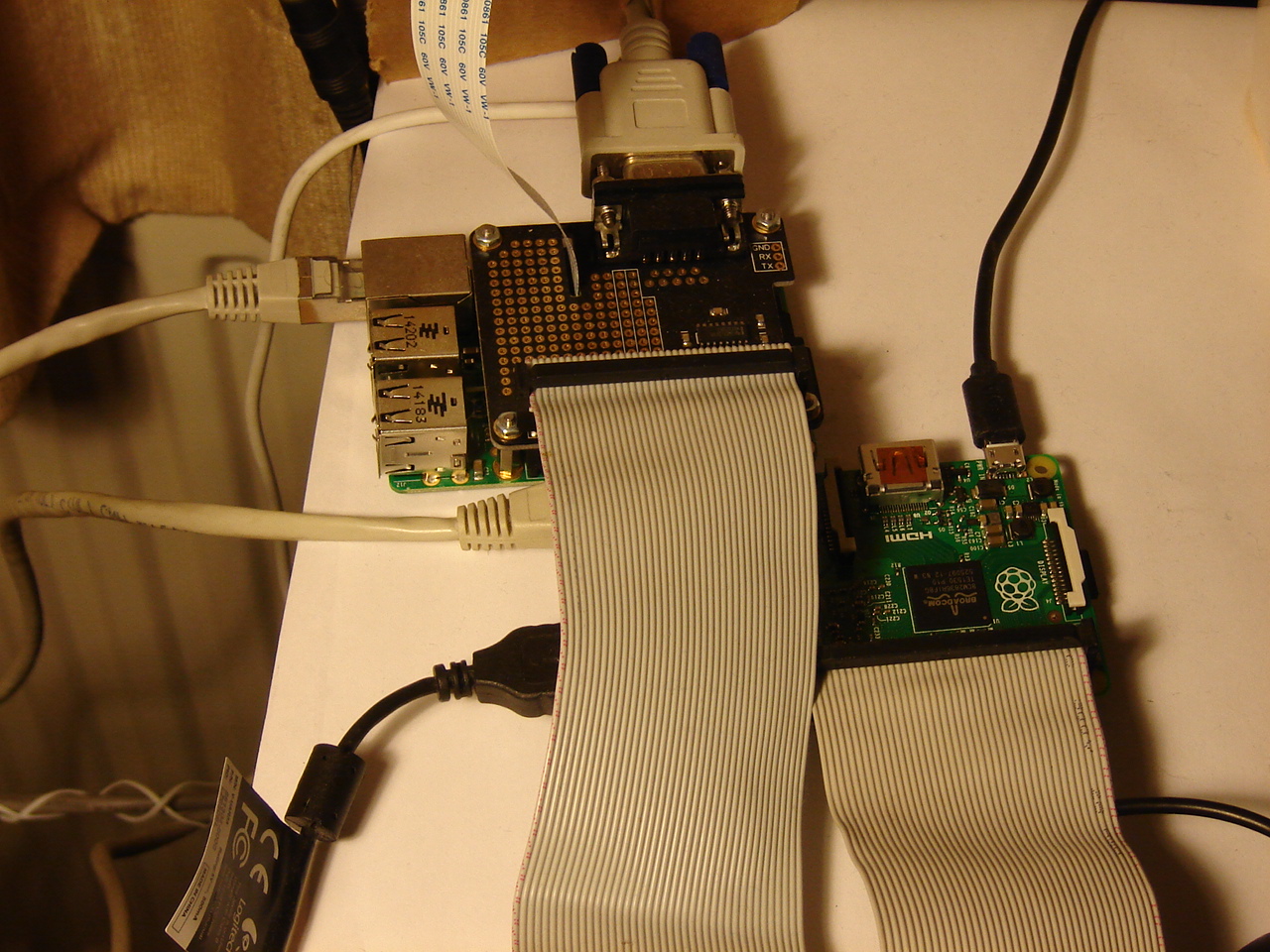
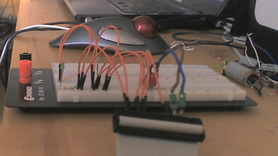
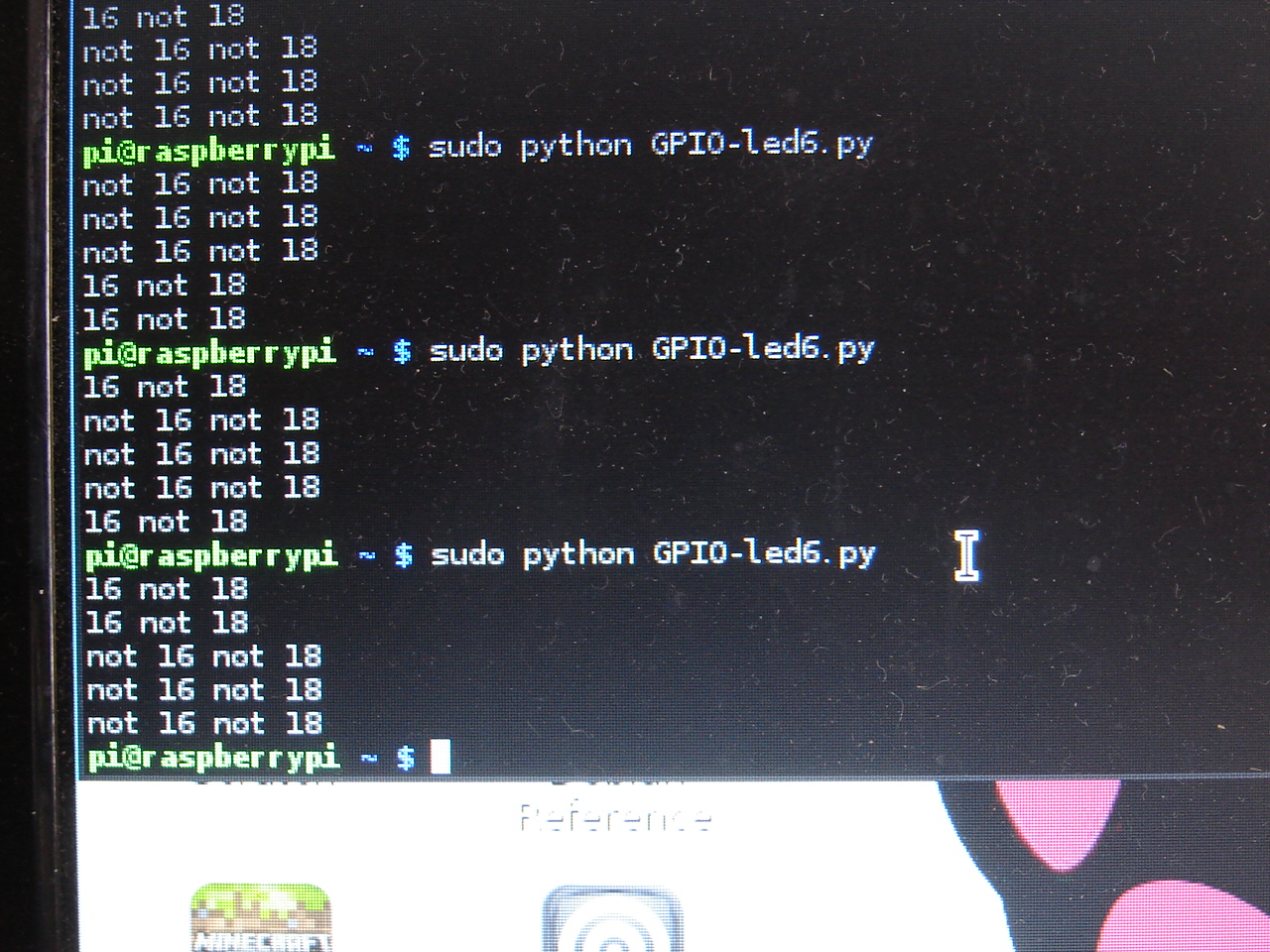
RPi: Last time, 1 LED kept burning and in an attempt to solve it...nothing works. Then with replugging (so: not replacing!) a few wires, all works (?!) Then, running the C++ version. LED 2 continues to burn, so there must be a bug in the C++ code. And there is a wrong LED setting: 4 - 5 - 3, where 3 = 1102 instead of 4 - 5 - 6 where 6 = 0112. [2 means binary. For completeness I should write 310 or 3D to indicate it's a decimal digit, but this is usually left out because we use decimal in daily life.] Then it shows that the control is the reverse from what is intended: the control by RPi2 stops the counter on RPi instead of starting it. Oops. Sigh. See the video.
Other problems are either with the RPi2 or with the operating system (Raspbian):
- during the experiments, ssh and vncserver were restarted. Usually, I can reconnect after a short time.
- at times, the restart doesn't happen.
When the restart doesn't happen, I need the HDMI video + keyboard + mouse to either kill processes or restart the RPi2. This means unplugging the those from the BB, which is a nuisance.
So I will try a different solution: buying another Serial Pi Plus and a null-modem cable and see if I can do without HDMI etc.
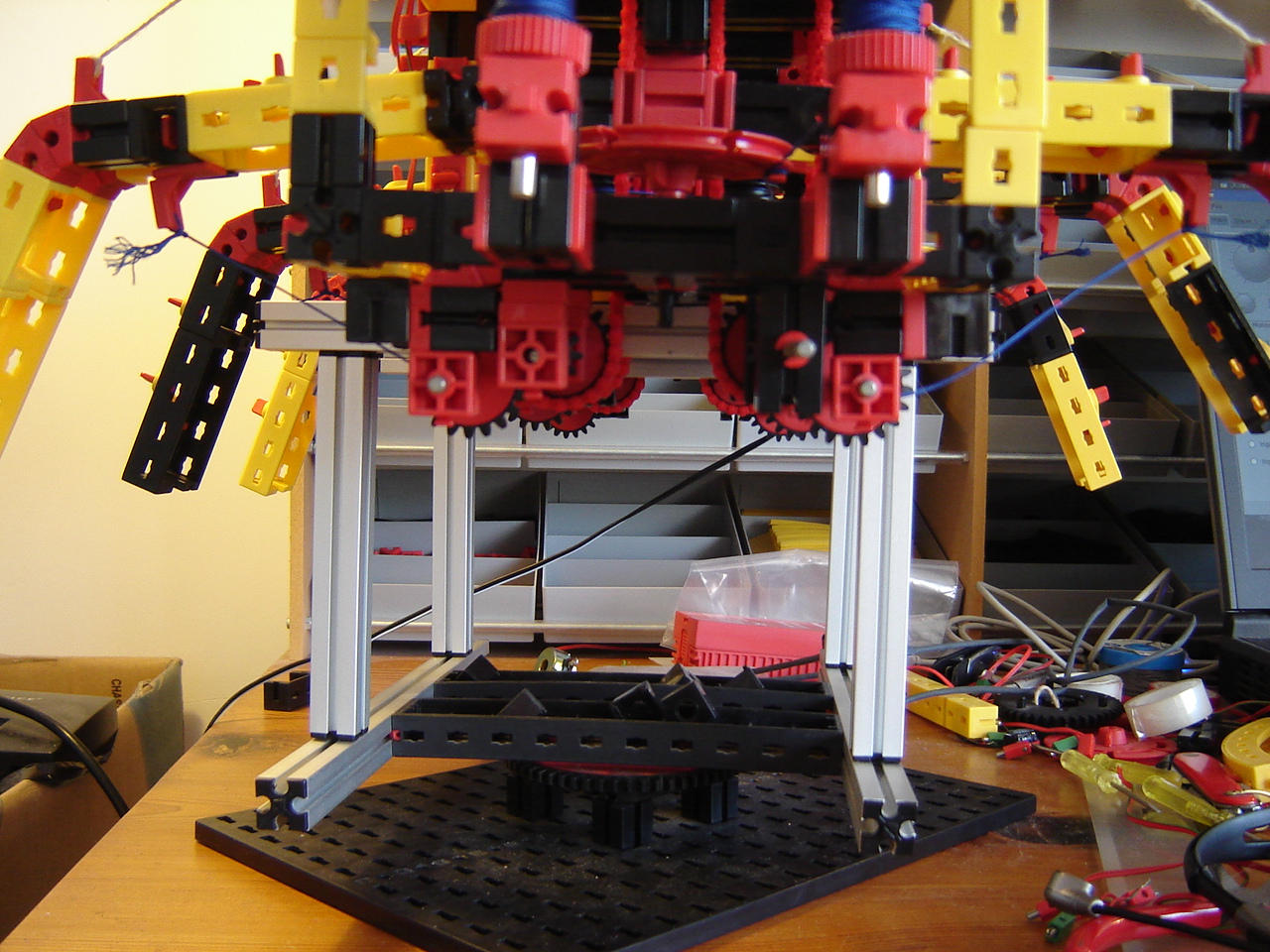
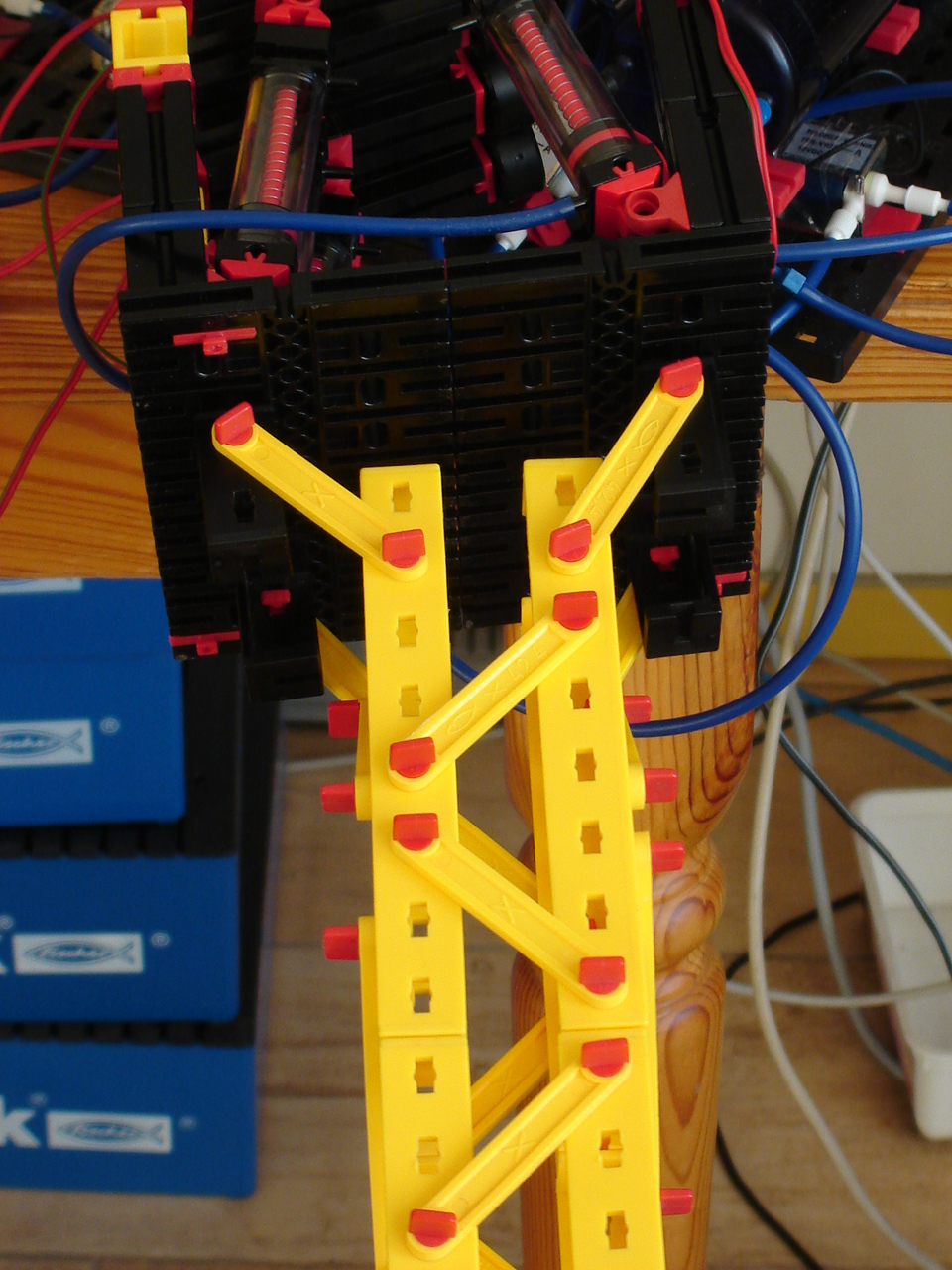
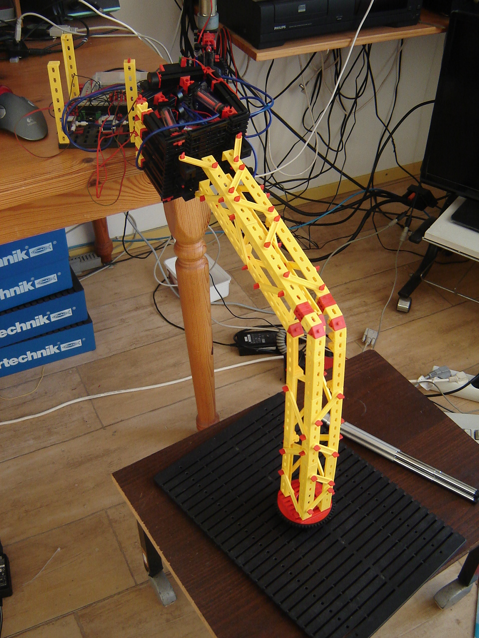
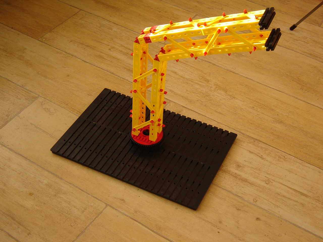
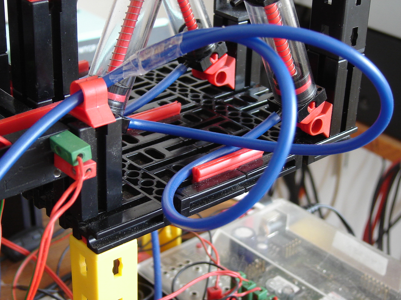
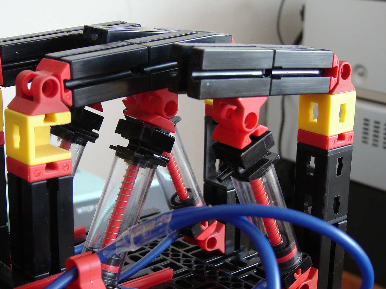
Hand: Continuing with the arm, I have to relocated the controller and the compression engine. But before I can do that, I will have to extend the tubes since they are at least 50 cm too short for after the relocation. However, I worry about the quality of the new silicon tubes: shabby doesn't sound promising as side note with the qualification. And the old quality tubes are too short. Also the upper part of the arm-base bends through because of the weight of the hand. To solve this, I place stabilizers. After some thinking, the extension solution may be the use of t-pieces and stoppers. See the video.
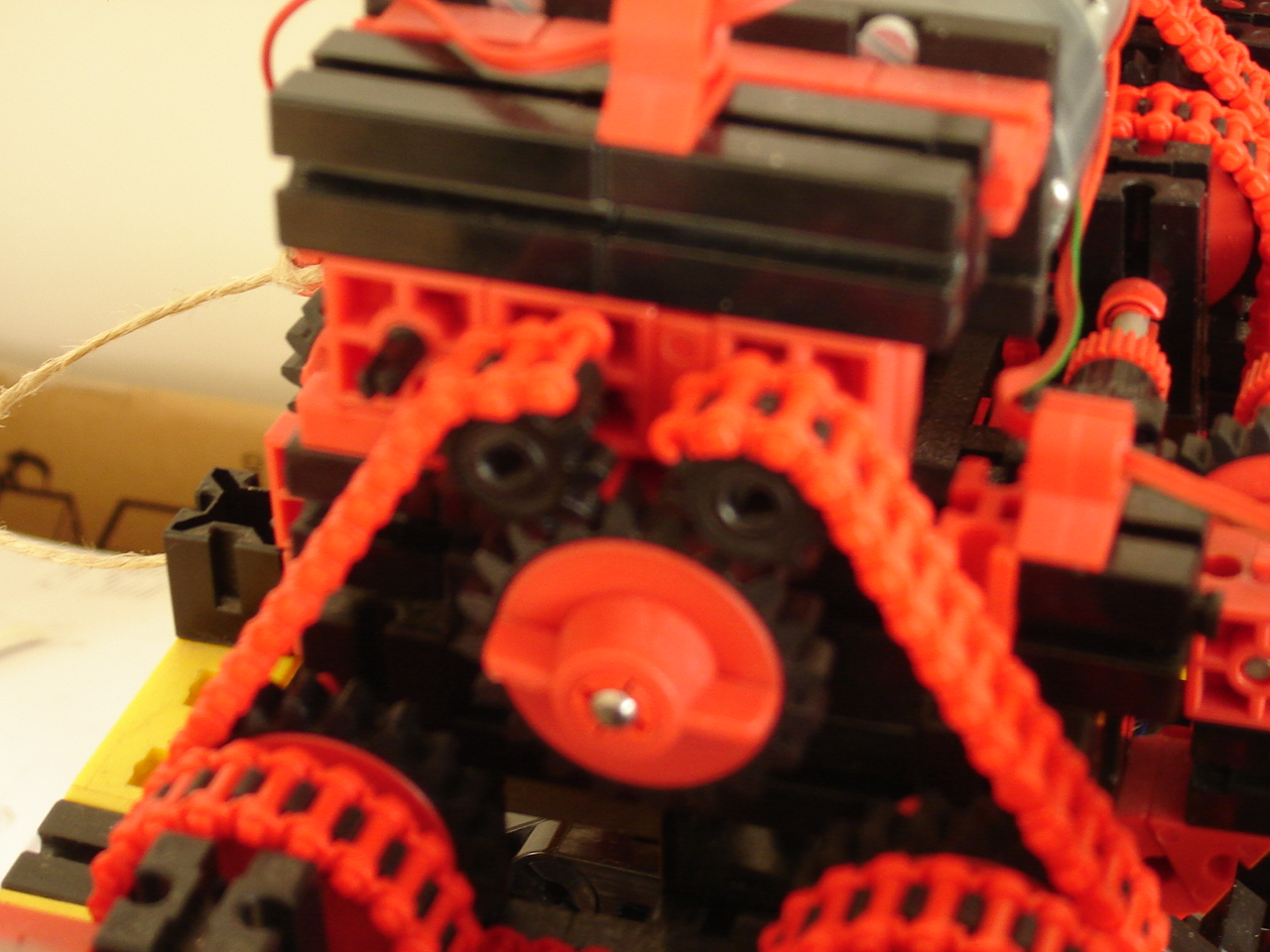
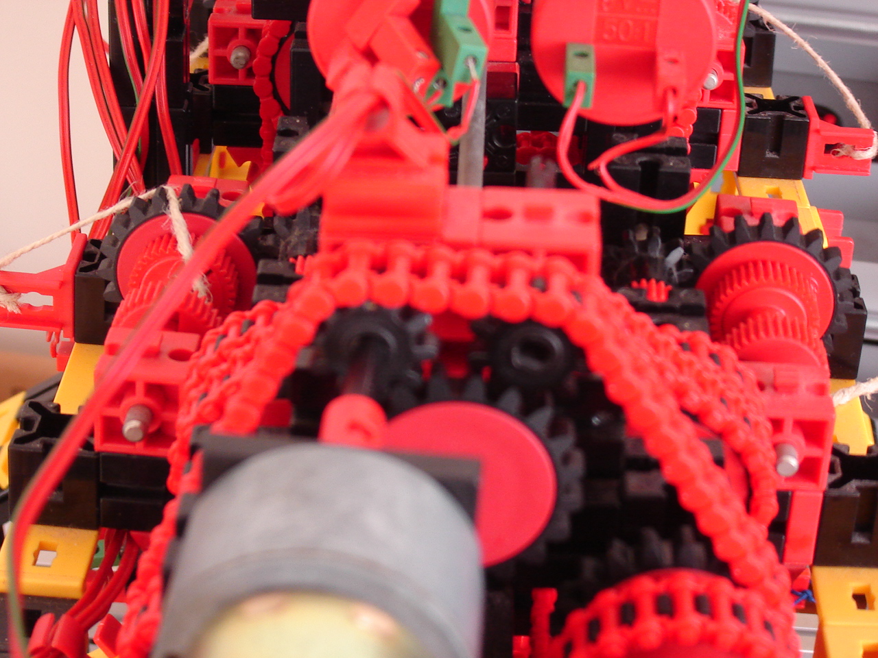
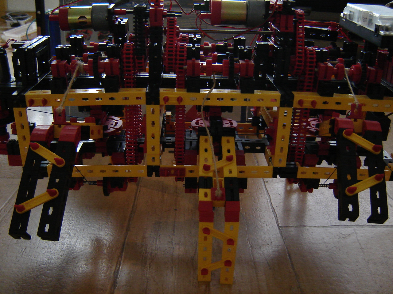
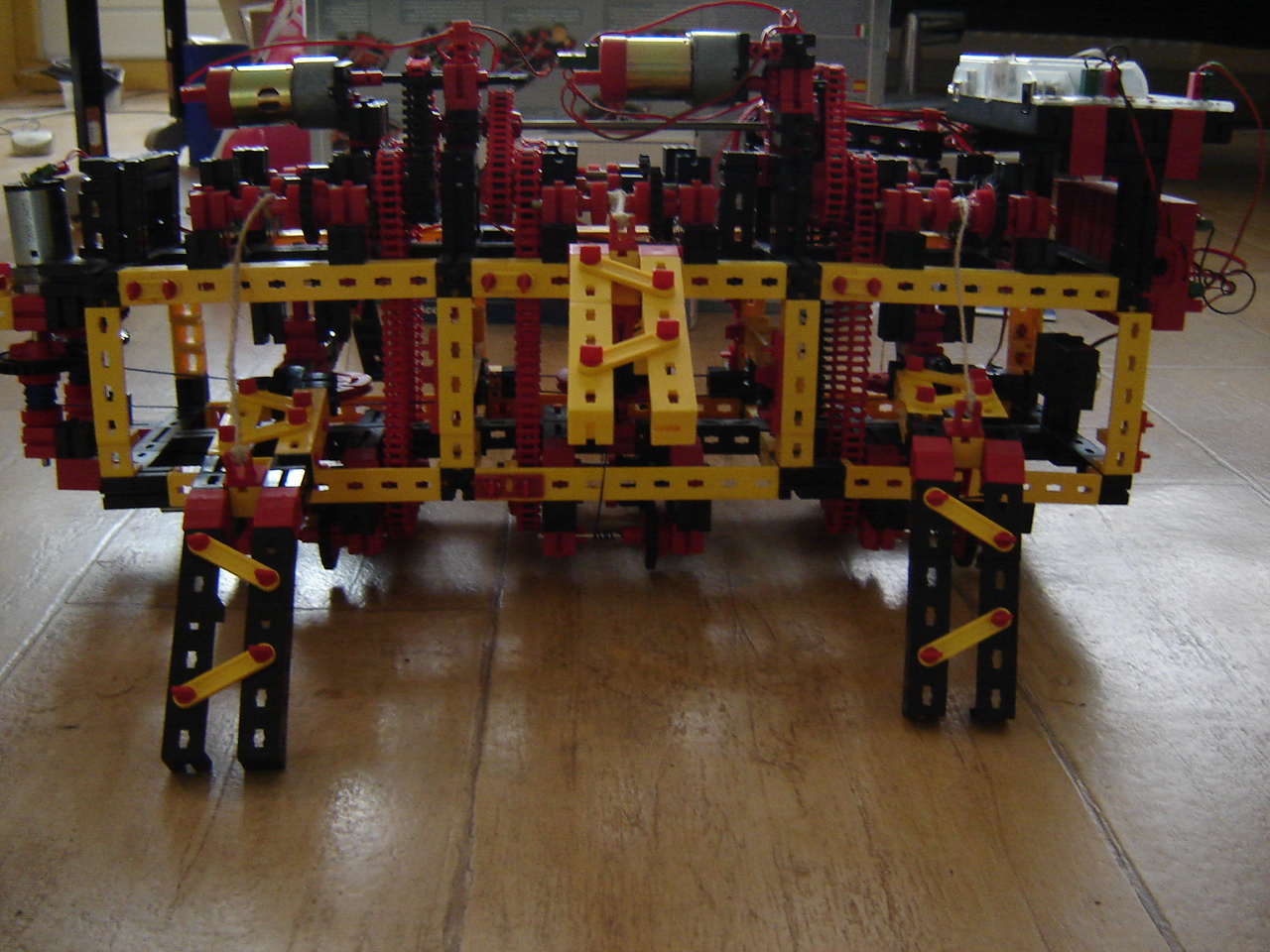
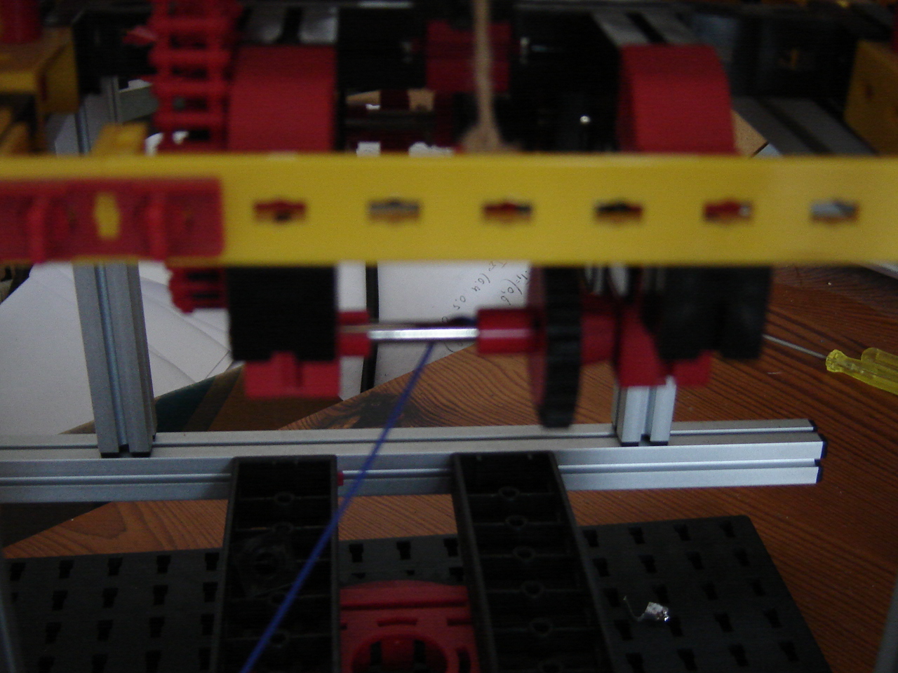
Mirft: Last time ended with the conclusion that a redesign of the gears was the only way to go on. However, the construction of the body is such that this is not possible. Another option is to add a supporting rod under the body that would prevent to body to leave its height. With a distance of 10 cm between the lower rig and the floor shouldn't be too difficult, but the question is what the rod should be made from. For now I take 2 iron rods and put one up front and one in the back.
1
 2
2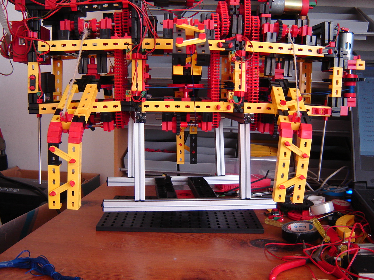
The floortest reveals that they're not connected very stable so I have to modify the horizontal motor setup to fix the back-rod.
3
 4
4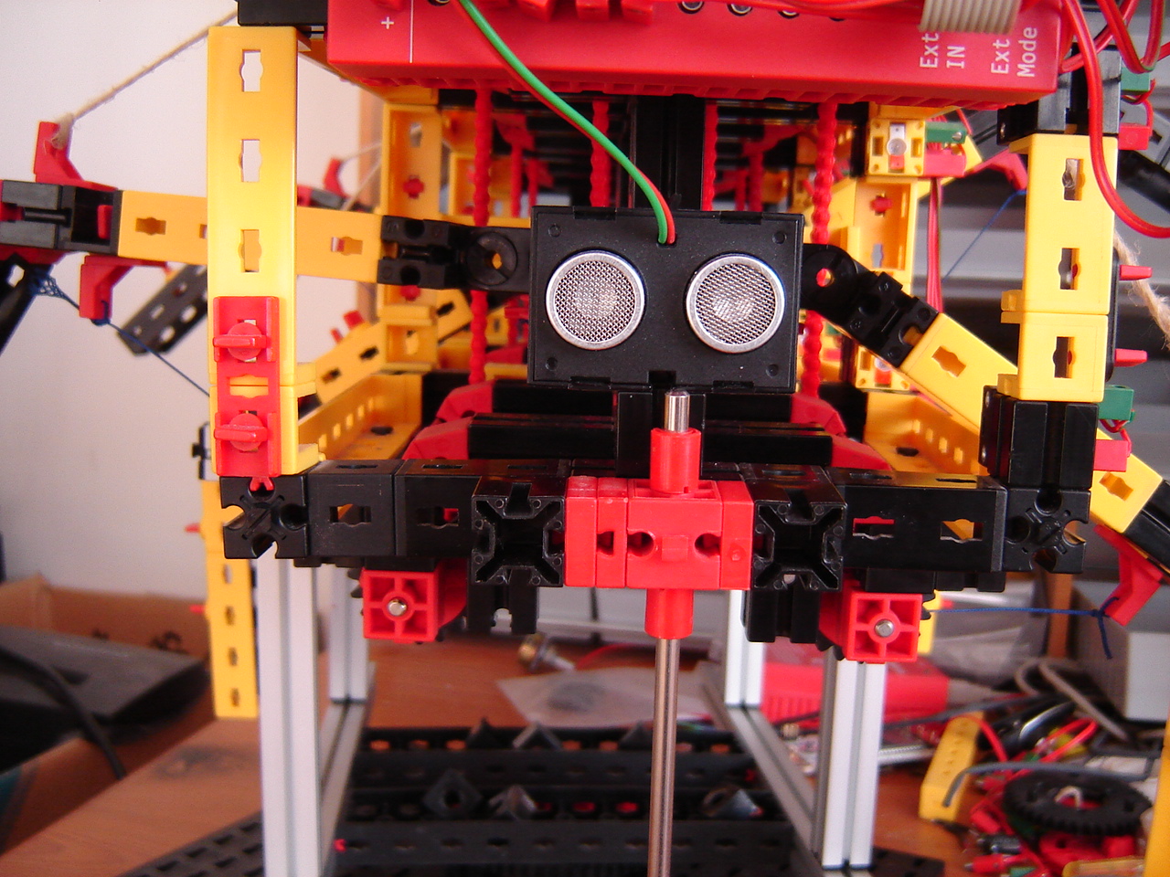
After this, the floortest goes fine: it stands on the rods and the legs prevent falling sidewards. See also this video.
25 December
Mirft: The failure of the last floor test is once again due to chain gears that are not fixed enough on the axes. When putting the legs completely horizontal it becomes obvious that the gearing has to change completely.
For the best result, the body obviously should keep its vertical position, while the legs go up and down. This can only be achieved with a decoupling of the vertical chains belonging to the same hip wheel. Ideally, 3 more motors should be added but since I lack the correct motors, I have to find a way to decouple the set of legs and change gears. Making things even more complicated than they already are. See the video.
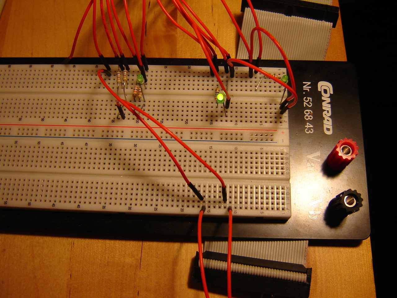
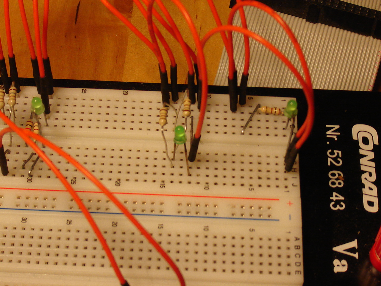
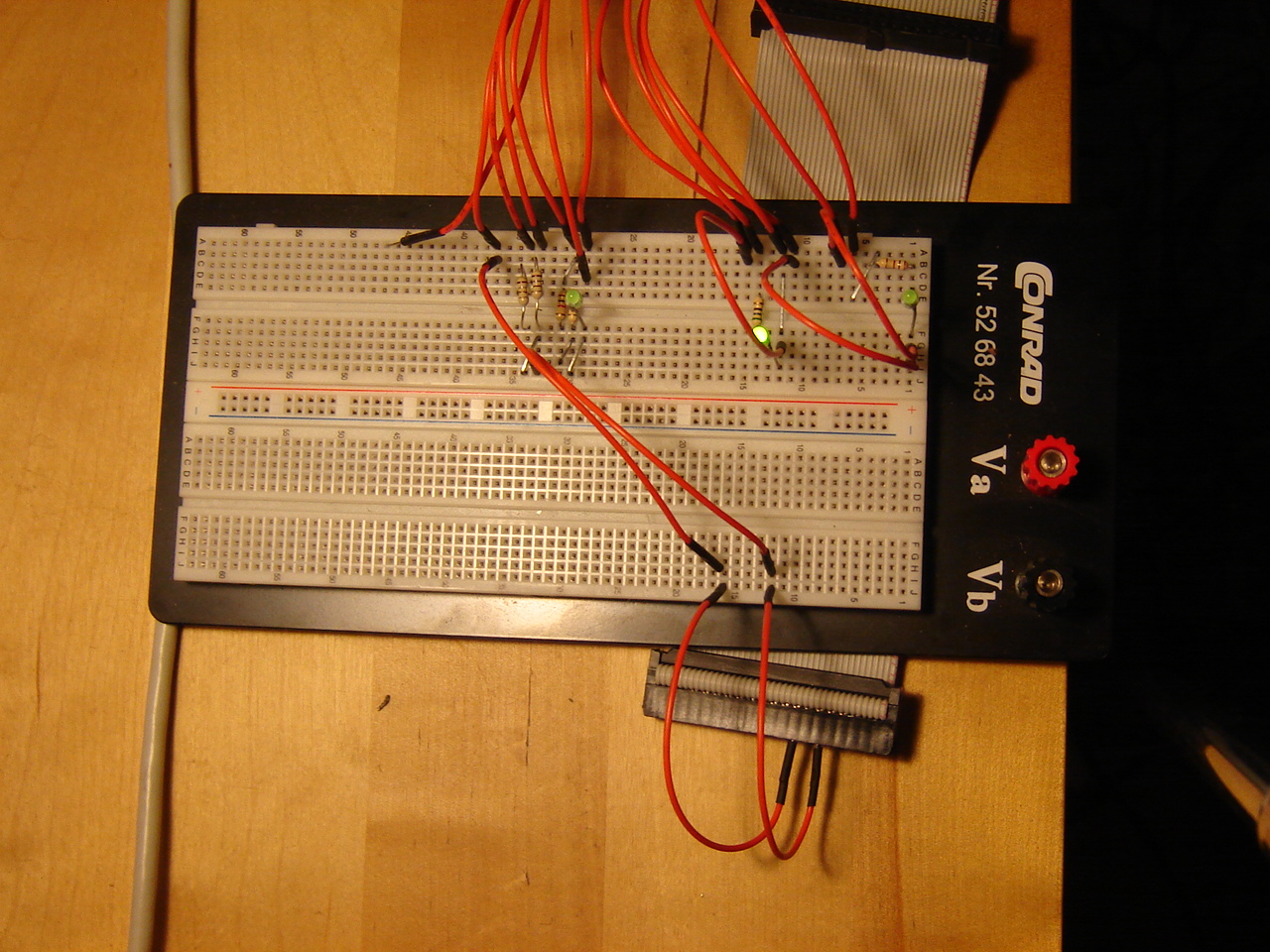
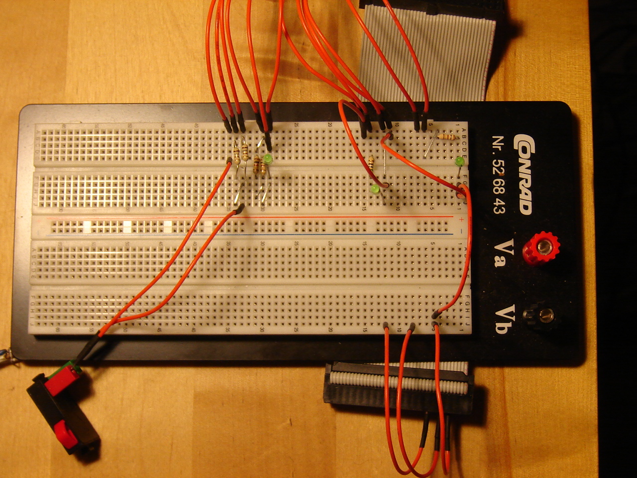
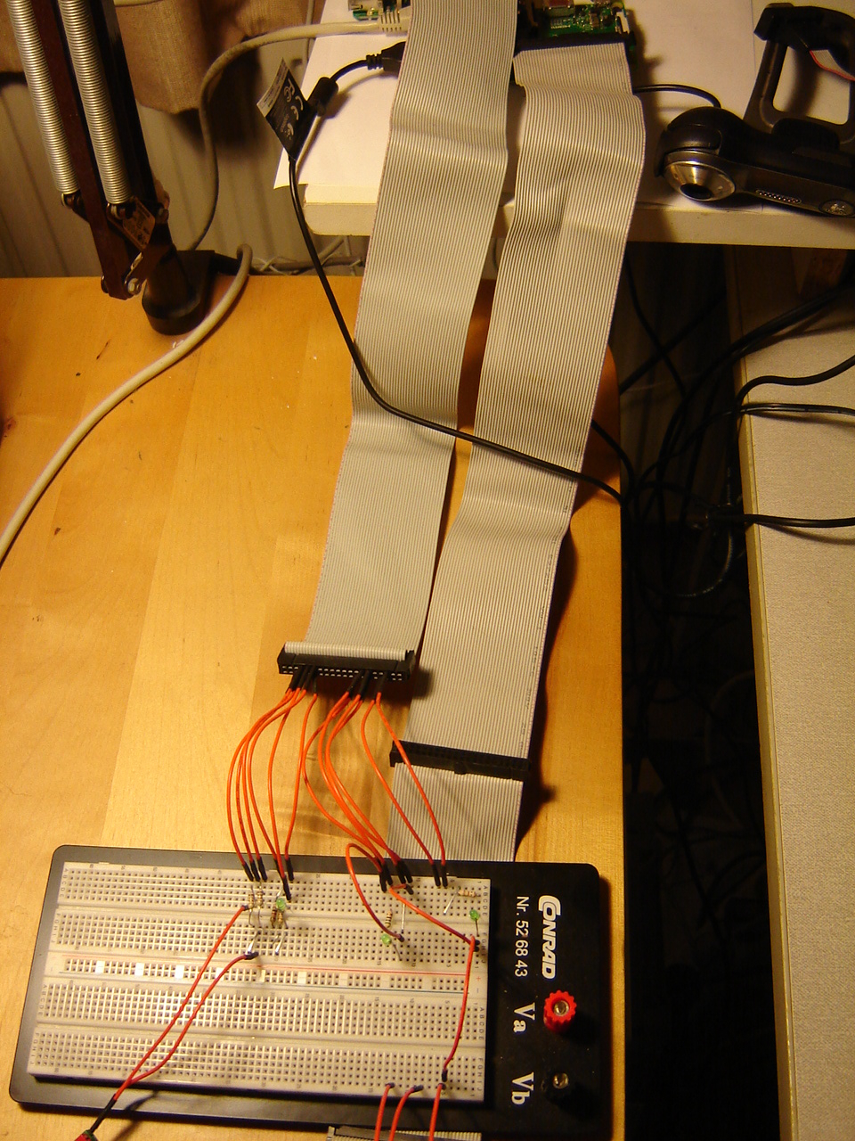
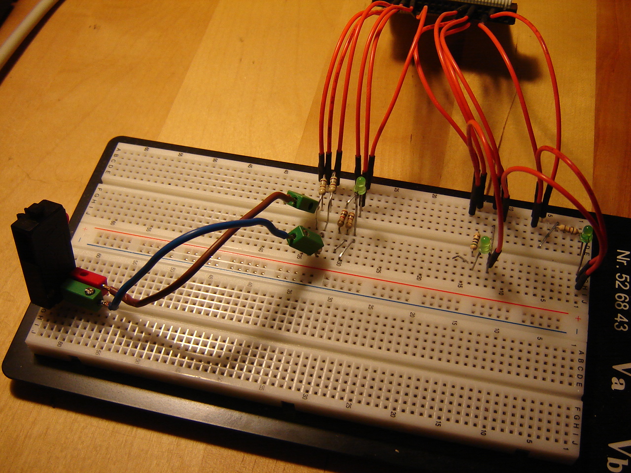
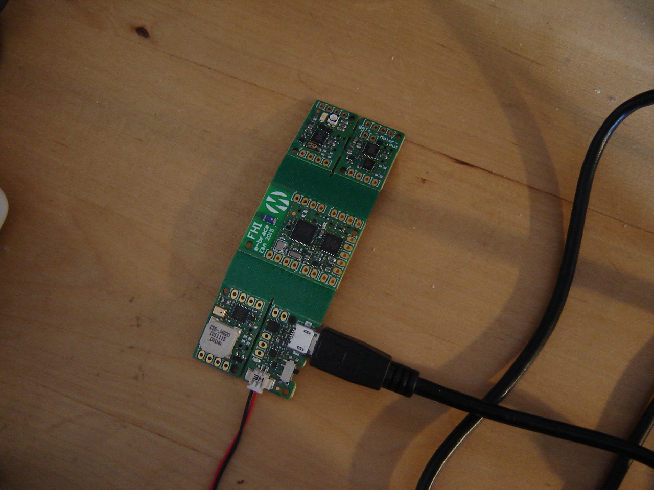
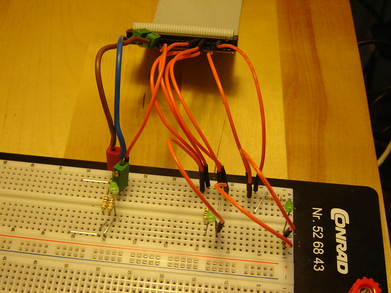
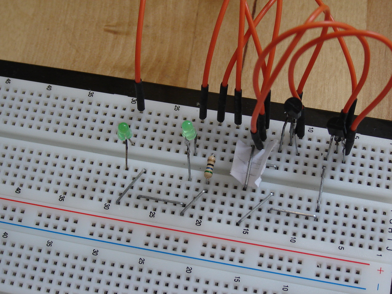
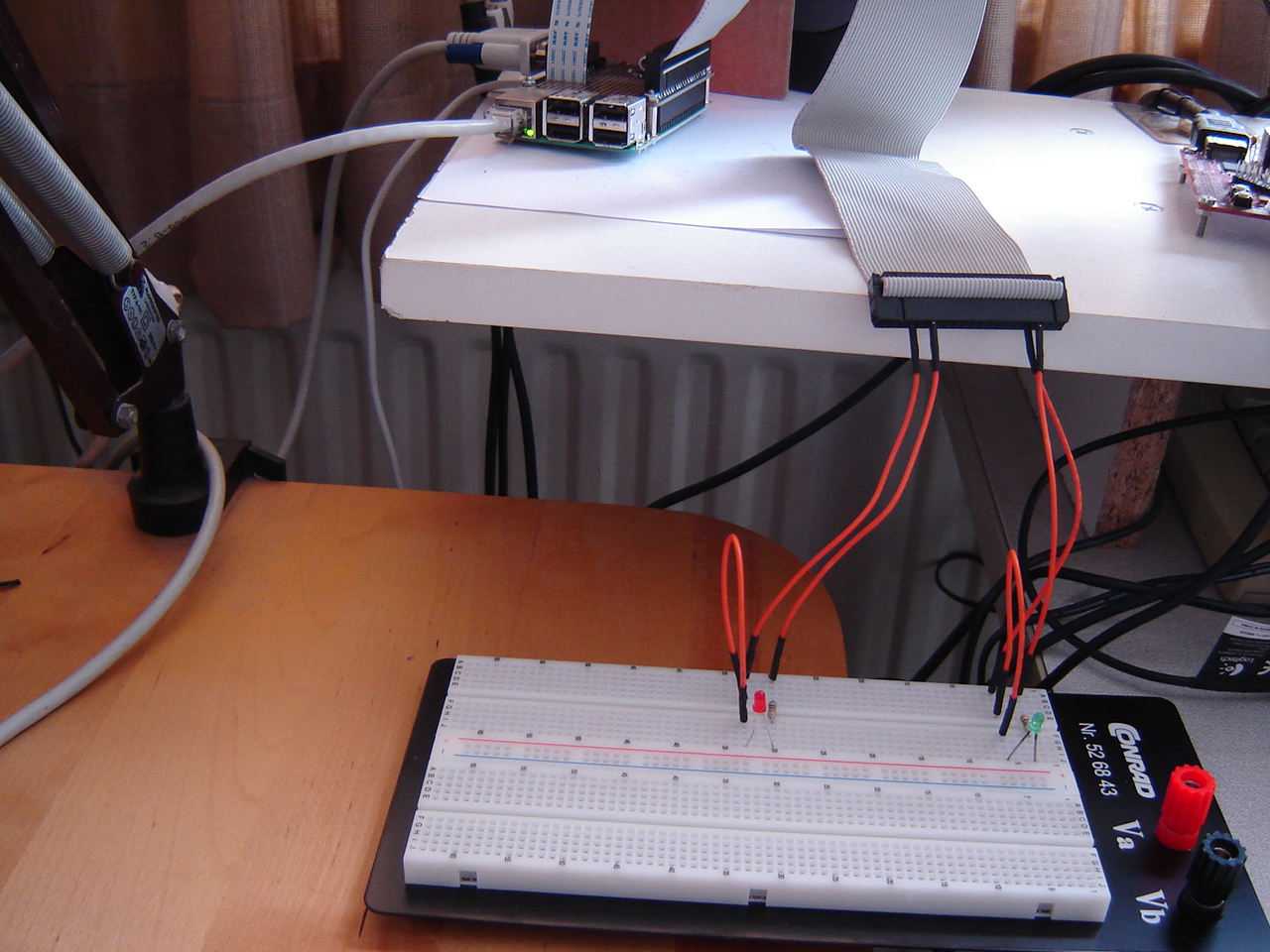
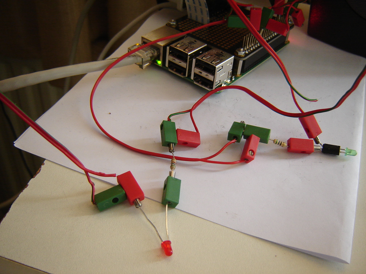
RPi: Since controlling RPi by RPi2 works in Python, it should work in C++ as well. So I port the RPi2 Python code to C++, which implies copying GPIOClass.cpp and GPIOClass.h from RPi and hardly ever goes without typos and other small errors. But after it compiles fine...there's a pin error from RPi: it seems like pin 12 is always high. However, running ./gpiotest on the RPi reveals that the pull-up resistor for pin 13 fails. See this video. Another test shows that pin 18 goes wrong. To be certain, I remove the flatcable from the GPIO and test again: only 15 fails. So I test again with the flatcable in place: wrong again. Some testing on the breadboard points in the way of the resistor between the LED and ground being not secured. Replacing the resistor by 2 resistors with longer wires (see 2nd picture) doesn't show effect, so more testing is needed.
Hand:With the algorithm so far complete, it's time to mount the hand to the arm. That brings new challenges: do I leave the fingers attached to the platform (for now: yes), how do I mount it on the arm: flexibly or rigid, are the tubes long enough (eh, no), etc, etc. See this video.
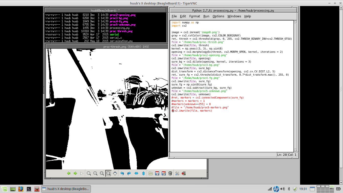
BB: Continuing with OpenCV, I still have an issue with bits and channels of images. watershed needs an 8-bits 3-channel image, while findContours gives a vector of points and no image. By which my conclusion is that this won't work. Conversion from vector to image won't work either: most attention on forums (with answers) goes from image to vectors. See this video.
18 December
Mirft: With focus on the upper gears, I manually adjust them: both the chain wheel and the cog wheel need to be fastened on the axis.
After that I have to manually adjust the vertical position of the legs again. And when all legs have been set, it's time for yet another test...or 2 and that doesn't go entirely as expected. See the video.
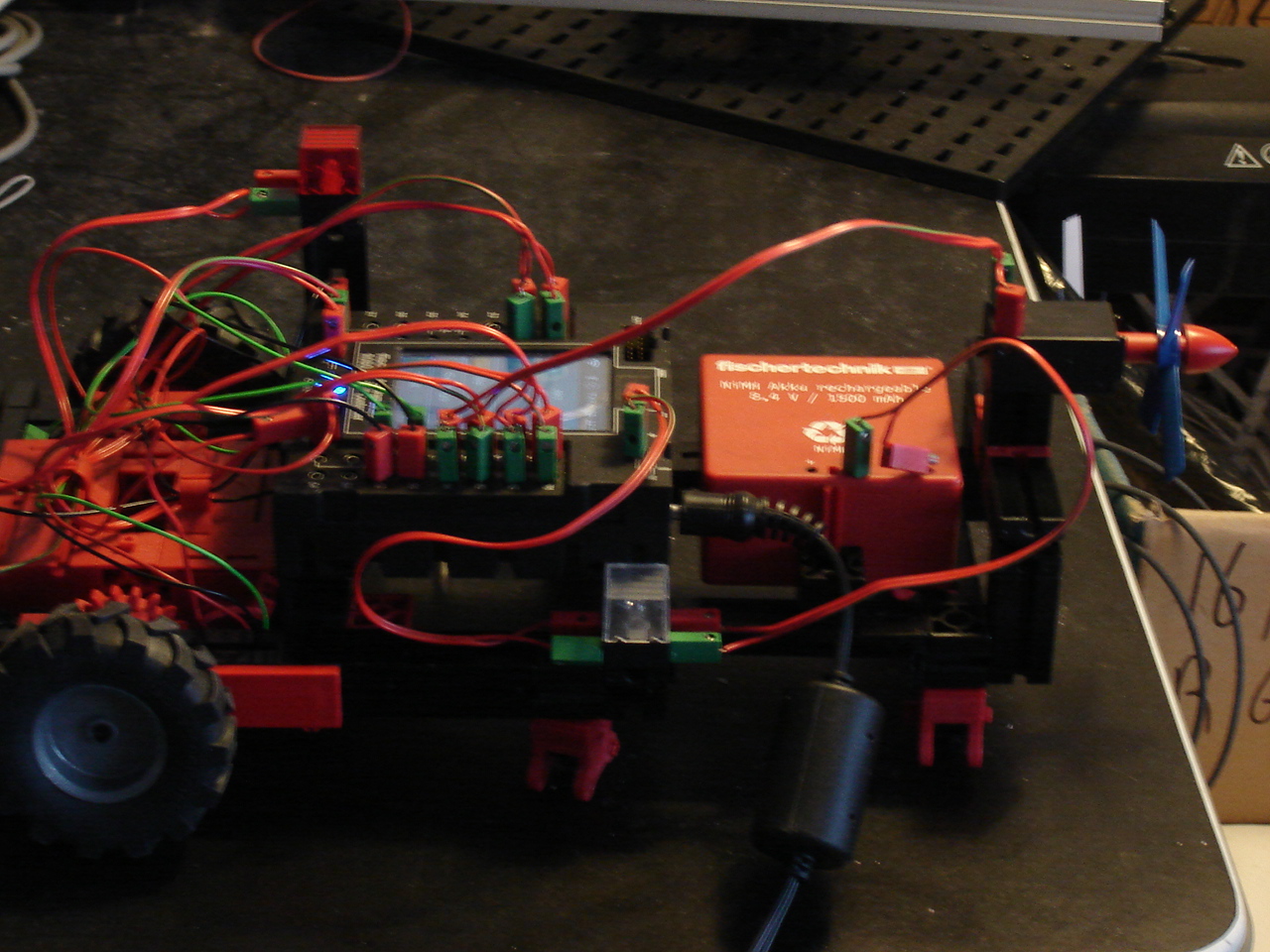
Discovery: As a funny, I added the fan from the TXT set to the robot. There's 1 motor output free, and the small motor exactly fits the fan. Unfortunately, the maximum speed in Python is only 512, so there's hardly any propulsion from it.
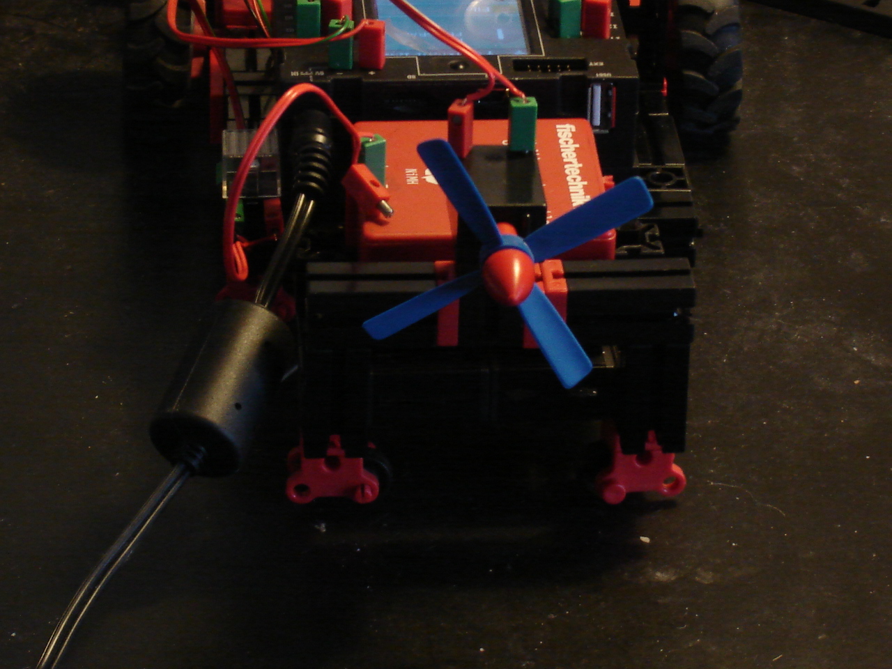
Recently, both a new firmware and new ROBOPro version came available and oddly, the main laptop doesn't recognize the TXT anymore. Hence there is no firmware update possible. However, the old laptop that I use for the TXT and Mydfir, does recognize the TXT. So after updating ROBOPro on there, the TXT firmware is nicely updated and should be capable for I2C and other fun stuff.
When adding the fan control to the code, there's no problem at first. But then the shit hits the fan, sort of. See the video.
RPi: After the first controlling test, the connection problems with the RPi2 aren't over yet. While the desktop via HDMI keeps running, the sshd and vncserver are far from reliable. For now I can do "service ssh restart", wait a bit and go on. A catch is that I have to do this via the desktop. I want to know if I can do this via serial as well but to do so I need another Serial Pi Plus and null-modem cable.
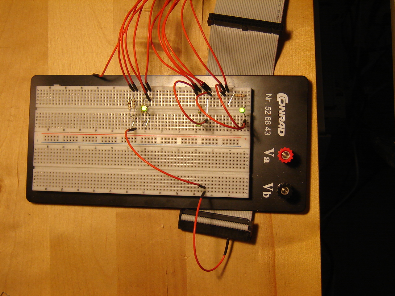
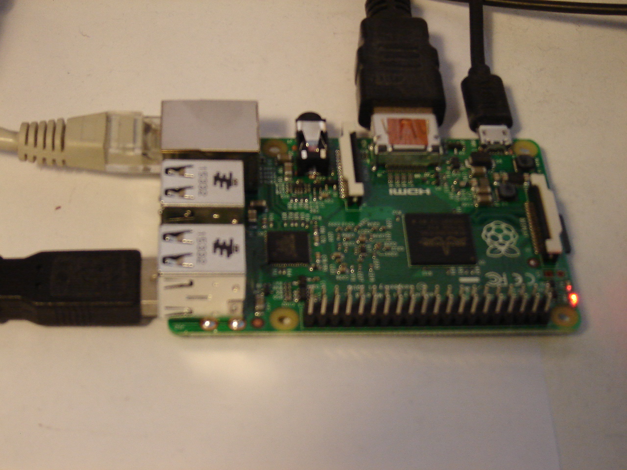
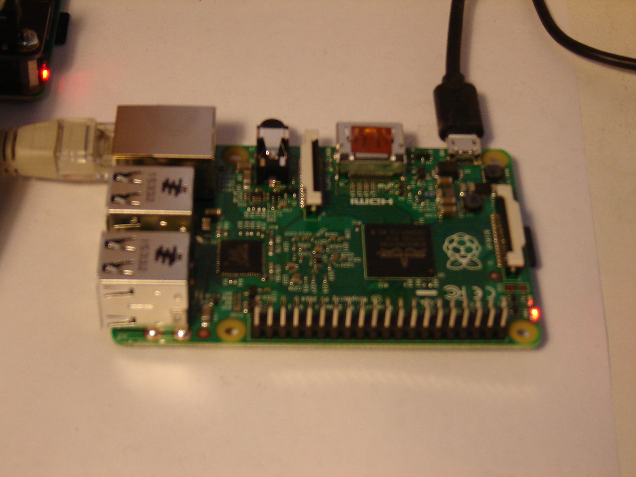
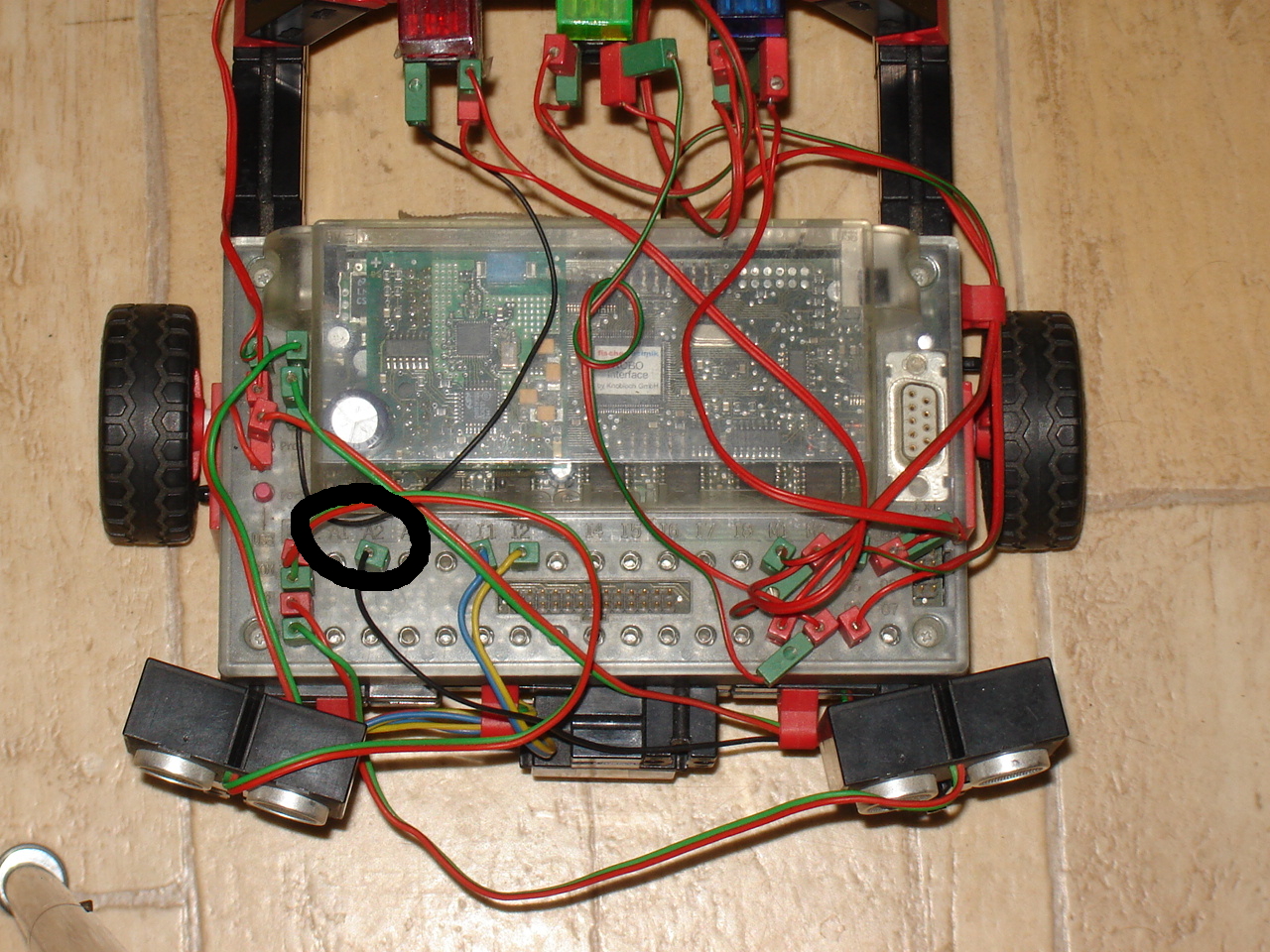
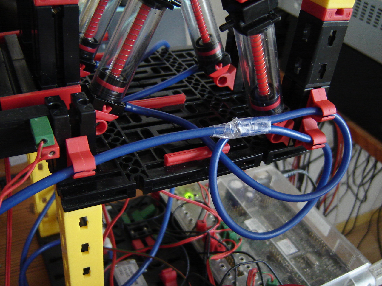
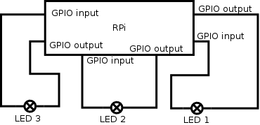
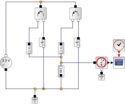
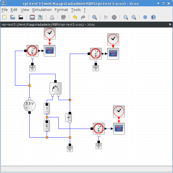
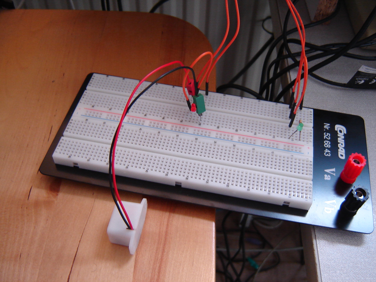
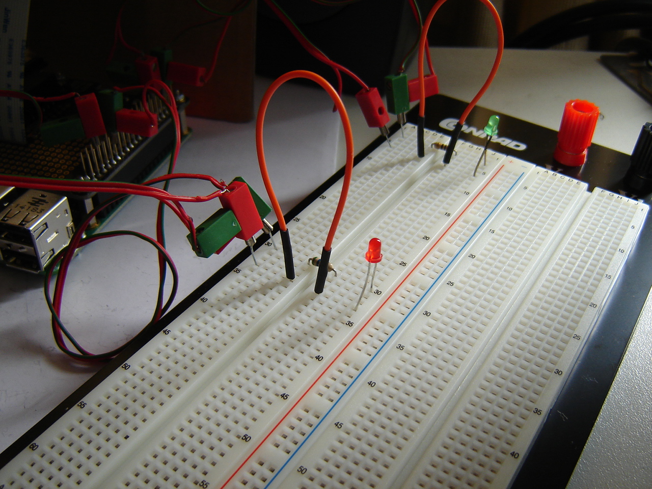
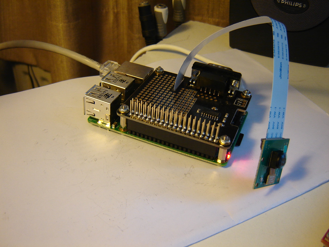
Back to the RPi2 controlling the RPi: it would be nice if I can have 2 controls: 1 letting the binary counter run (pin 12), and 1 to reverse it (RPi2 pin 16 -> RPi pin 37). See the picture.
For this to work, I have to extend the counter code for reverse counting and read/detect the "reverse counting" signal. Although the code looks good, the result isn't as expected. See the video.
BB: Continuing with OpenCV: since the recorded image is 8 bits, I have to convert it into 32 bits. However, this turns out to be more complicated than I first thought: changing instructions and limitations of instructions cause problems.
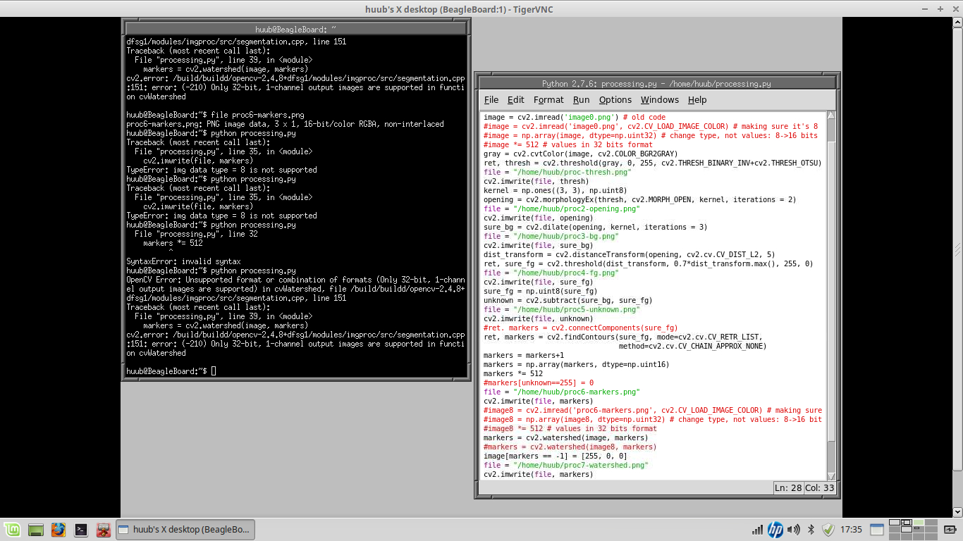
See this screencast video.
11 December
Discovery: After finding that the code doesn't exactly do what I want (stopping at meeting an object), I find another instruction: read out the number of pulses from the motor. With this, I can have the motor stop prior to reaching the maximum set distance. See this video with screencast and a few experiments.
RPi: Continuing with the video tests, I find that raspivid -t0 makes that the RPi cam keeps recording until ctl-c is pressed. To make things easier, I put the raspivid command into a 1-line executable script using chmod +x.
On the RPi2 side, it seems to hang again. So I have to find out why. Simplest solution is cycle power, but obviously that's not meant to be. But after the power cycle, it hangs again. Time for more rigorous measures: download a newer image and reinstall. Then it turns out I have to do an extra action to make use of the full 16 GB: expanding the filesystem. Although that gives me a 24% use, it unfortunately doesn't stop the "hanging". Which isn't a total hanging, because the HDMI video obviously doesn't hang at all.
Despite all this, the next step is using the RPi2 to replace the switch of the 3-bits binary counter and see what happens. See this video and this RPi camera video.
Hand: It's time to extend the software so it can move more multiple fingers at the same time. Then it's also nice if the fingers switches are at the same position. So with a slight shift of the tube connection, the switches look like being in line. Which doesn't make it much easier to touch 2 at the same time though. See this video.
BB: Continuing with OpenCV, I find that OpenCV v3 won't do the job yet without cross-compiling from source. Since this always has a chance for dependency-hell, I find that findContours can do the job as well, although it needs more parameters: a mode and a method. After some old-fashioned trial-and-error the correct value for mode is found: RETR_LIST becomes cv2.cv.CV_RETR_LIST and for method. method is found in a similar way. With this solved, another problem shows up using watershed: the number of bits in a picture. See this video.
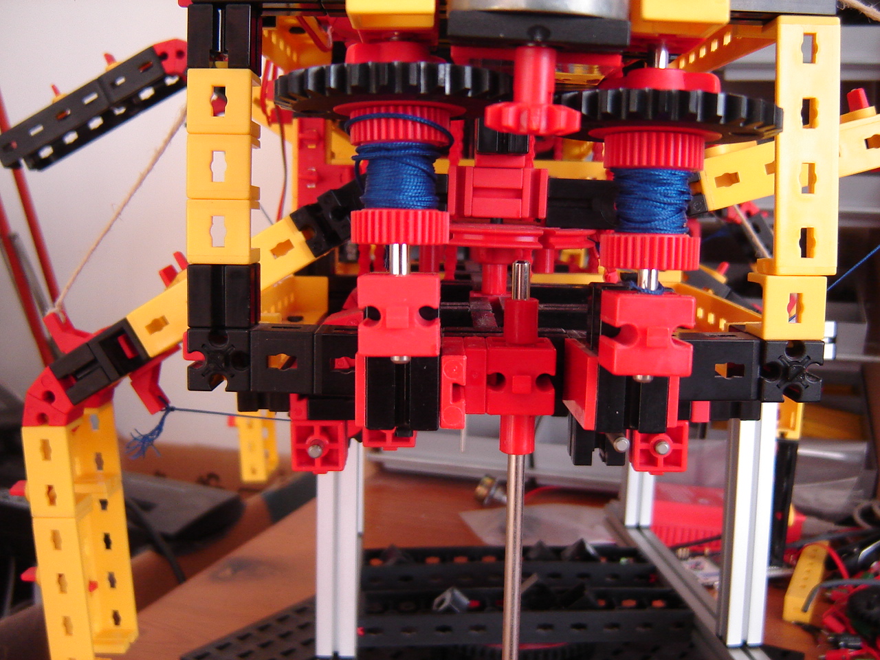
Mirft: Time for a chain check: are the 6 vertical chains equally long? Well, no...see the pictures. It's not hard to imagine that the legs don't move equally with unequal chains.
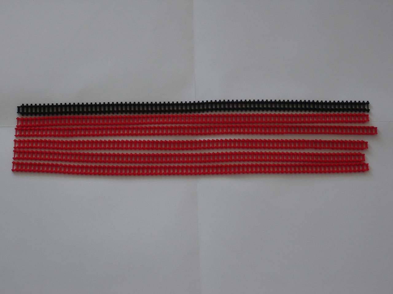
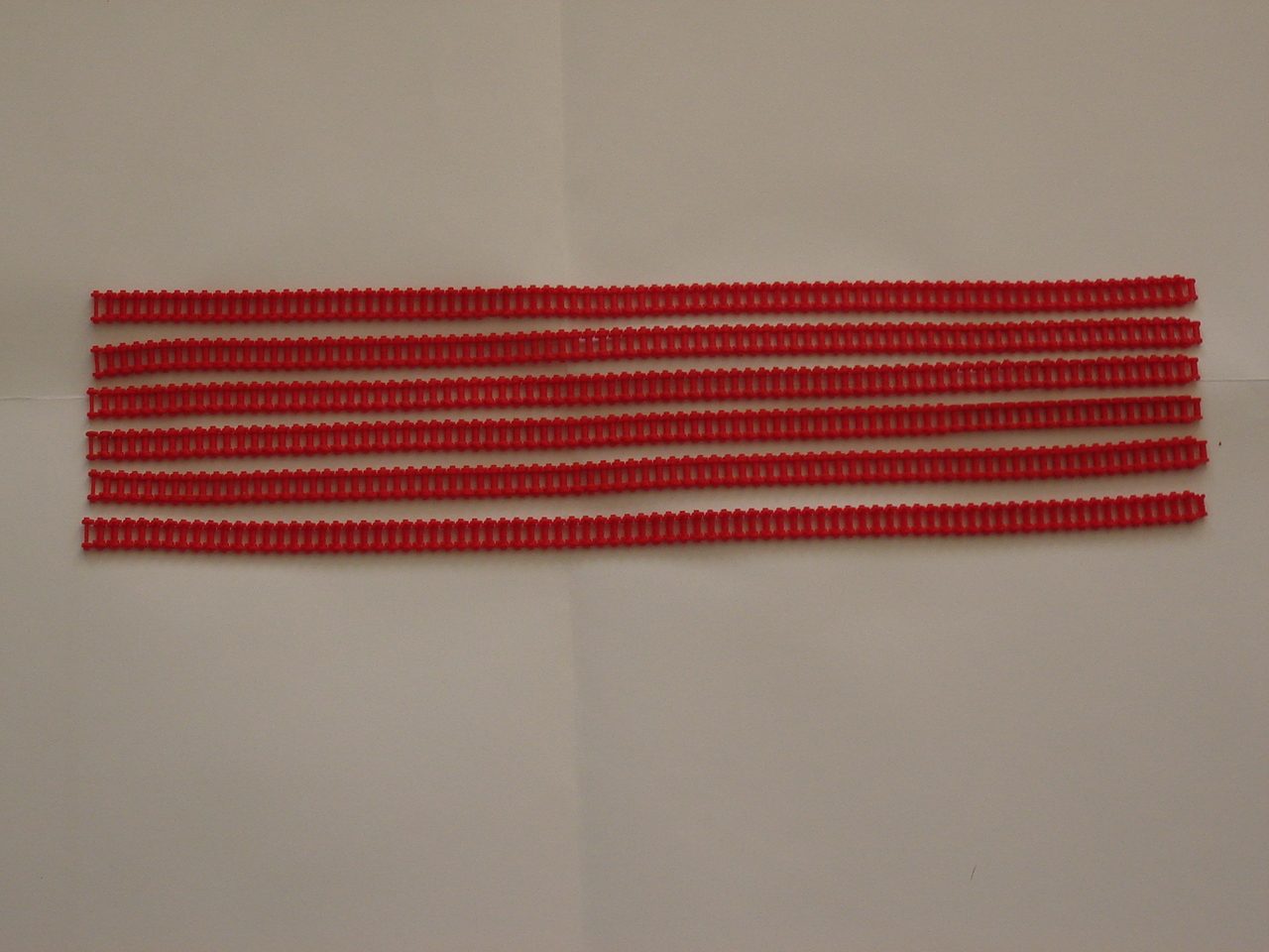
Then looking at the top chains, it reveals that those aren't equally long either. But aafter equalizing the top chains...there are some remarkable results:
See this video. So the end result is that with the chains fixed...the top gears seem to need some fixing.
4 December
RPi: Continuing with the RPi2, something is strange. Using the df -k command to check the used disk space, it shows 89% used with barely anything on it. The RPi only shows 66% used with quite a few user files on it. And the SD card for the RPi2 is twice as large. So something is very odd.
To do another "split-screen" camera test, I connect the webcam to the RPi2, install guvcview and find that it works fine, with a catch. After this, it's time for a first test with the RPi2, the webcam for "splitscreen" and controlling the breadboard. A combination being more complicated than I thought. See this video.
Mirft: After the last floor test, it showed that the wide position of the legs is not a good idea considering the weight of Mirft. However, a closer look at the angles between upper- and lower leg shows that there's a flaw in 2 legs: not 2x30 degrees but 2x15+1x7.5. Ouch. By lack of 30 degree parts, I do with 15 degree parts, making the legs in the same angle, although a bit longer. Then I try the floor-test again, see this video. After using the openshot editor, the audio turned out to be bad and further attempts didn't improve it. So in the end, for this video I went back to the Youtube editor, where I found I can add transitions between sections as well.
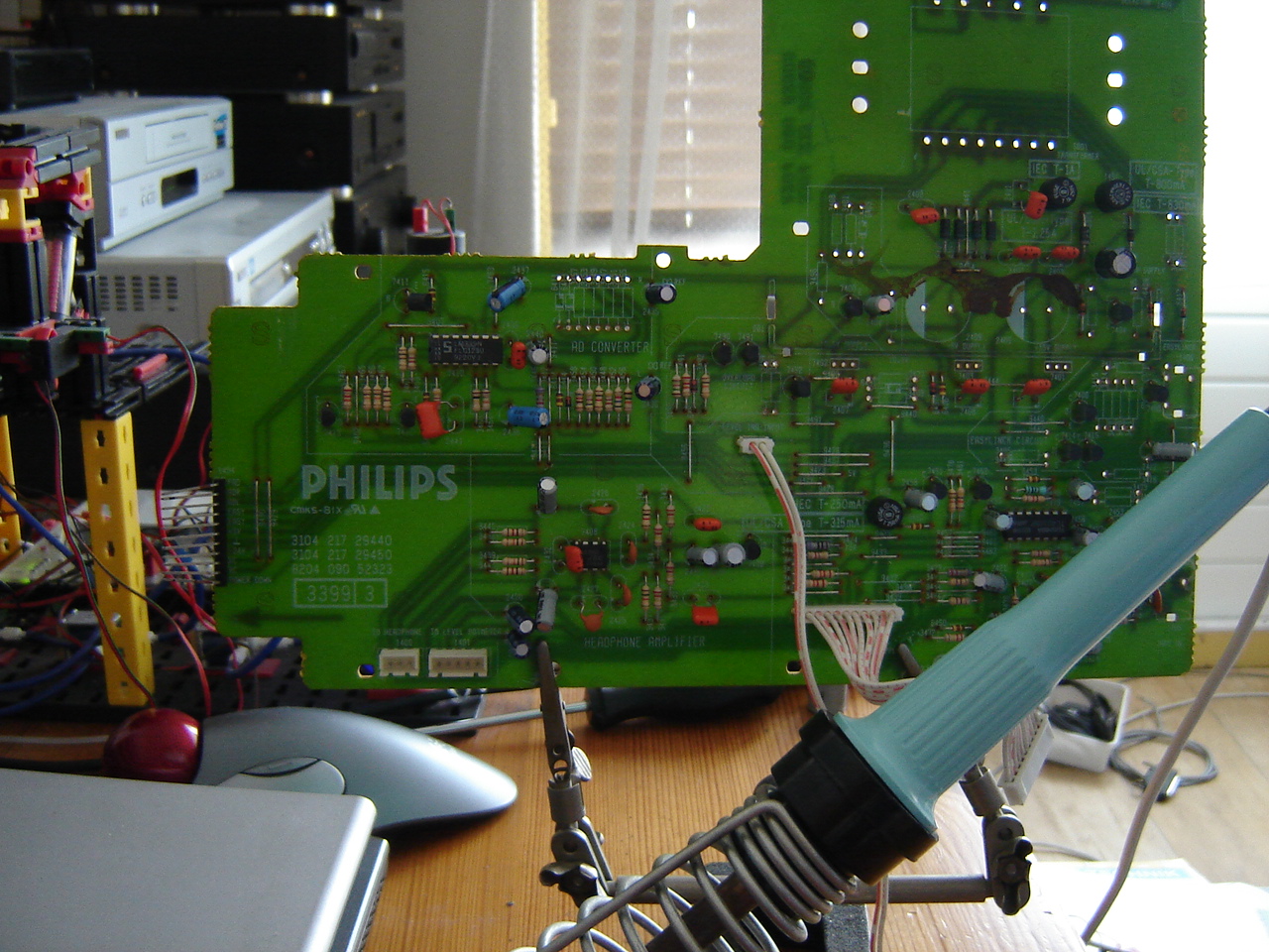
BB: As previously shown, the core of this board can't be used anymore. Still it's worth to see how OpenCV can deal with images using Python. But it doesn't go as smooth as expected. As an experiment, I also try to use tightvncserver so I can make screencasts. This turns out to work quite well.
Since this works via the network instead of the HDMI video, I can use a larger resolution than 800x600. See this video.
Hand: With the hand having 4 fingers and a thumb, it would be only logical if it would be possible to activate more fingers at the same time. For this the code has to be extended, which is easy enough. What turns out to be not as easy is pressing more than 1 switch at the exact same time. See this video.
27 November
RPi:Continuing with the kind-of split screen, I try the fischertechnik USB camera. See picture. Again using a resolution of 800x600 and discover 2 facts: 1) the image frame is much larger 2) there's a delay of at least 1 second between action and the actual display of the image. This delay wasn't there with the webcam and smaller image frame. Another test using 640x480 shows the same frame and delay. So apparently it's the camera that matters. See this video.
With the arrival of the RPi2, it's time for another series of experiments: RPi+RPi2.
To set it up, I have to completely disconnect the BB, because I need the HDMI video cable, the mouse and the keyboard. After installing Raspbian for ARMv7, VNC needs to be installed. After this, the setup will be more or less the same as with the RPi. For now it will lack the SerialPi board and RPi camera.
Setting up the RPi2 gave a nice quick experience although not everything was the way I expected. See this video. Then another nasty surprise: after reboot, I fail to login via keyboard. After using the router to determine the RPi2 IP address, I decide to use ssh and find I can login. So the password does work after all. Then starting vncserver again, and I can do whatever I like, until vncserver quits. Having the ssh terminal open, I can easily restart it but it's obvious that this isn't the way it's supposed to go. Another effect I notice, is that vncserver starts again.
After all this, I disconnect the complete USB keyboard/mouse/WLAN stuff and HDMI cable: they go back to the BB.
Mirft: It's time to modify the last 2 legs into stable ones and test again. What it turns out that some of the gears on the chain axis are a bit loose and the gears that hold 1 of the chains are moving freely. Oops. After fixing this, the chains and gears problems seems to be solved, but the floor-test reveals yet another problem. See this video or this video (an offline created "director's cut" version).
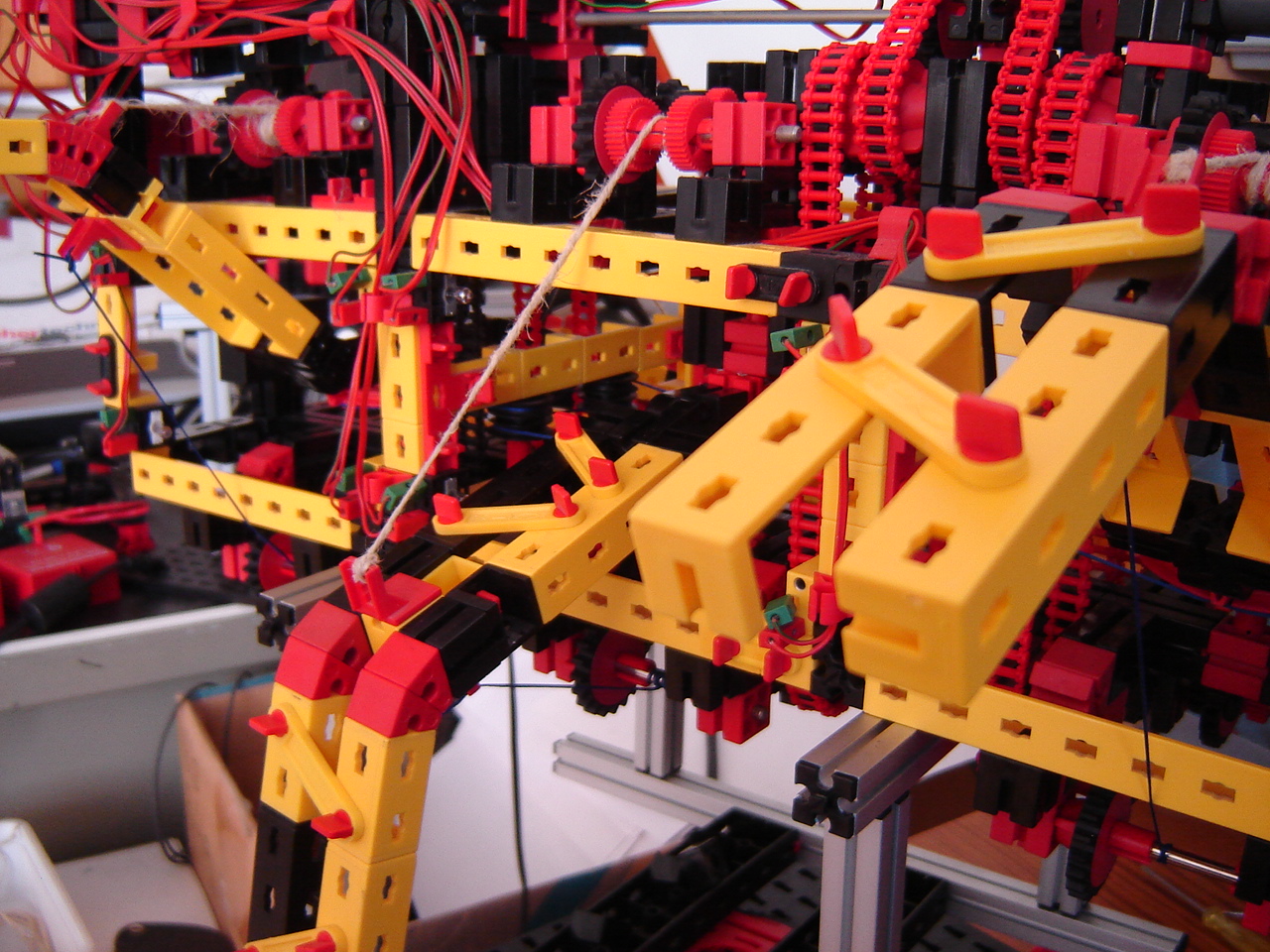

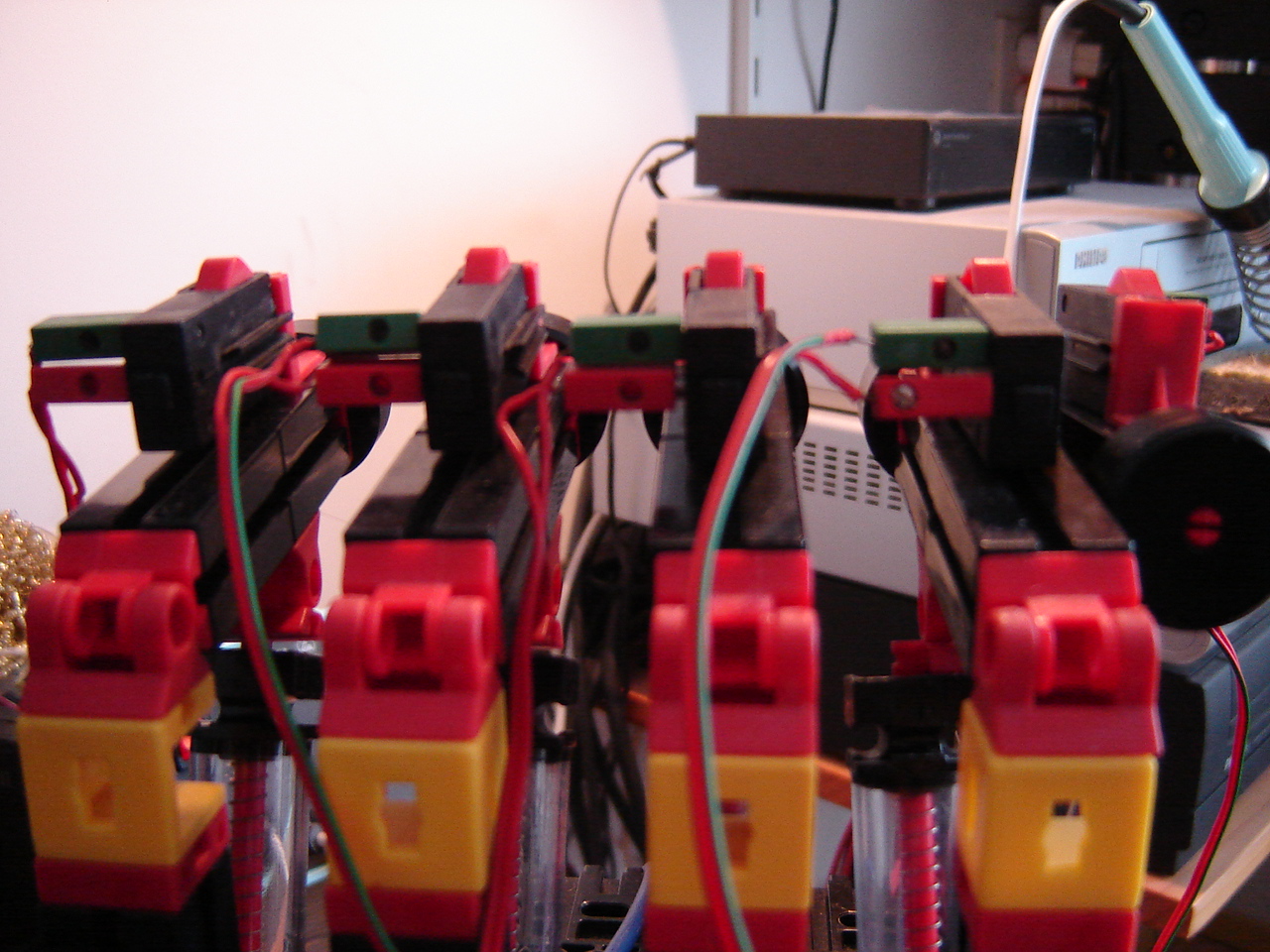
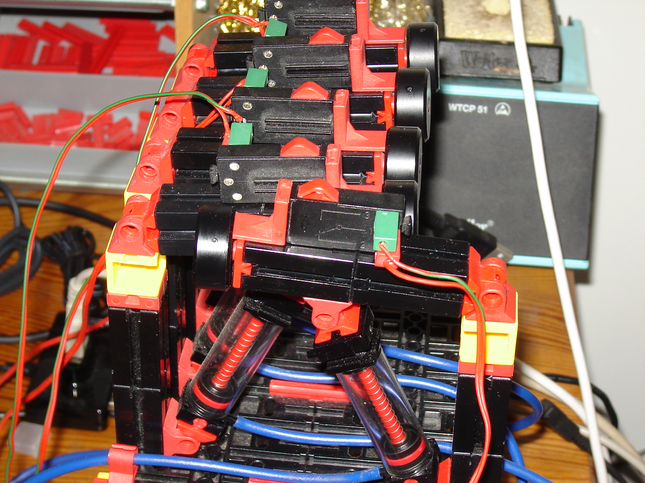
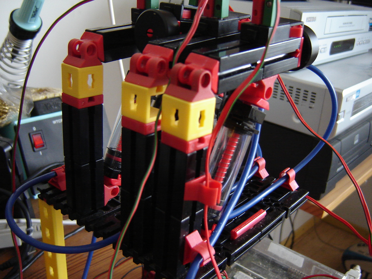
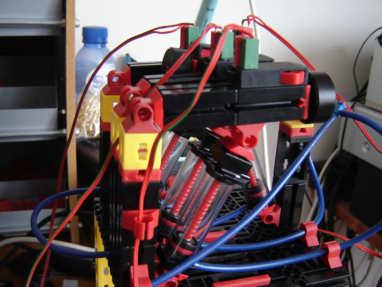
Hand:After repositioning the fingers into 4 fingers and 1 thumb as in a real hand, I need to reposition the 3 existing valves as well so I can add the 2 new ones. This brings a spatial problem which is solved by elevating the compression chamber. See the pictures and this video.
BB: So far, I've used the BB for some image and video capture experiments in combination with Python. This delivers avi videos that look like 6x speed up.
There are several disadvantages of this BB version (Classic Revision C4). The maximum display resolution over the HDMI port is 800x600. Also the 250MB RAM is a serious limitation, as well as the 16 GB SDHC memorycard as "harddisk". To save memory, I use the fvwm2 desktop which works fine. However, it looks like it's current use is coming to an end as there are signature verification errors during updating the operating system: Ubuntu 14.04 LTS armhf.
The only other use of this board would be for the Digital Signal Processor to process images. But that requires the seriously outdated 2.6 Linux kernel and an equally seriously obsolete DSP driver set. Hence, out of the question.
Software: I've started to publish my source code, not on Github but here on my website. Because of the quantity of my projects Github is too much work.
20 November
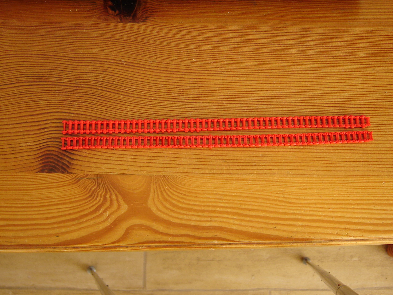
Mirft: Focussing on chains, I corrected 1 chain by taking 2 links out of it (see picture) and found that another suspected chain is actually of the correct length.
First it shows that the support of the gearing is pressed down, but after correcting this slipping still happens. So more to be investigated. See this video.
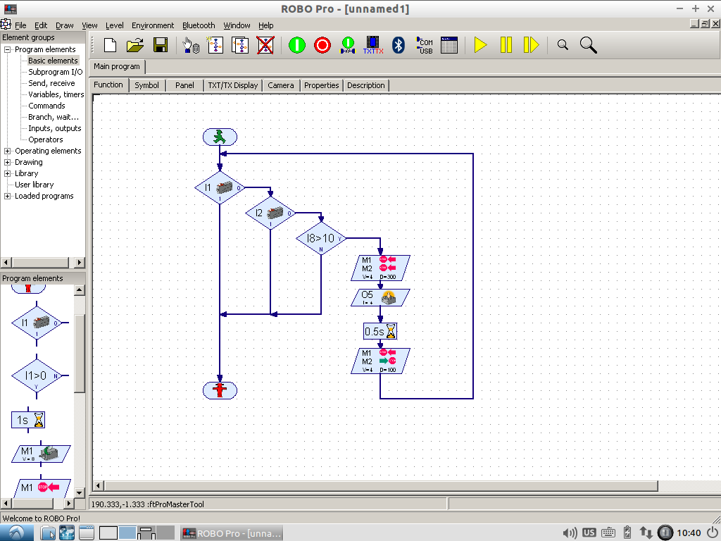
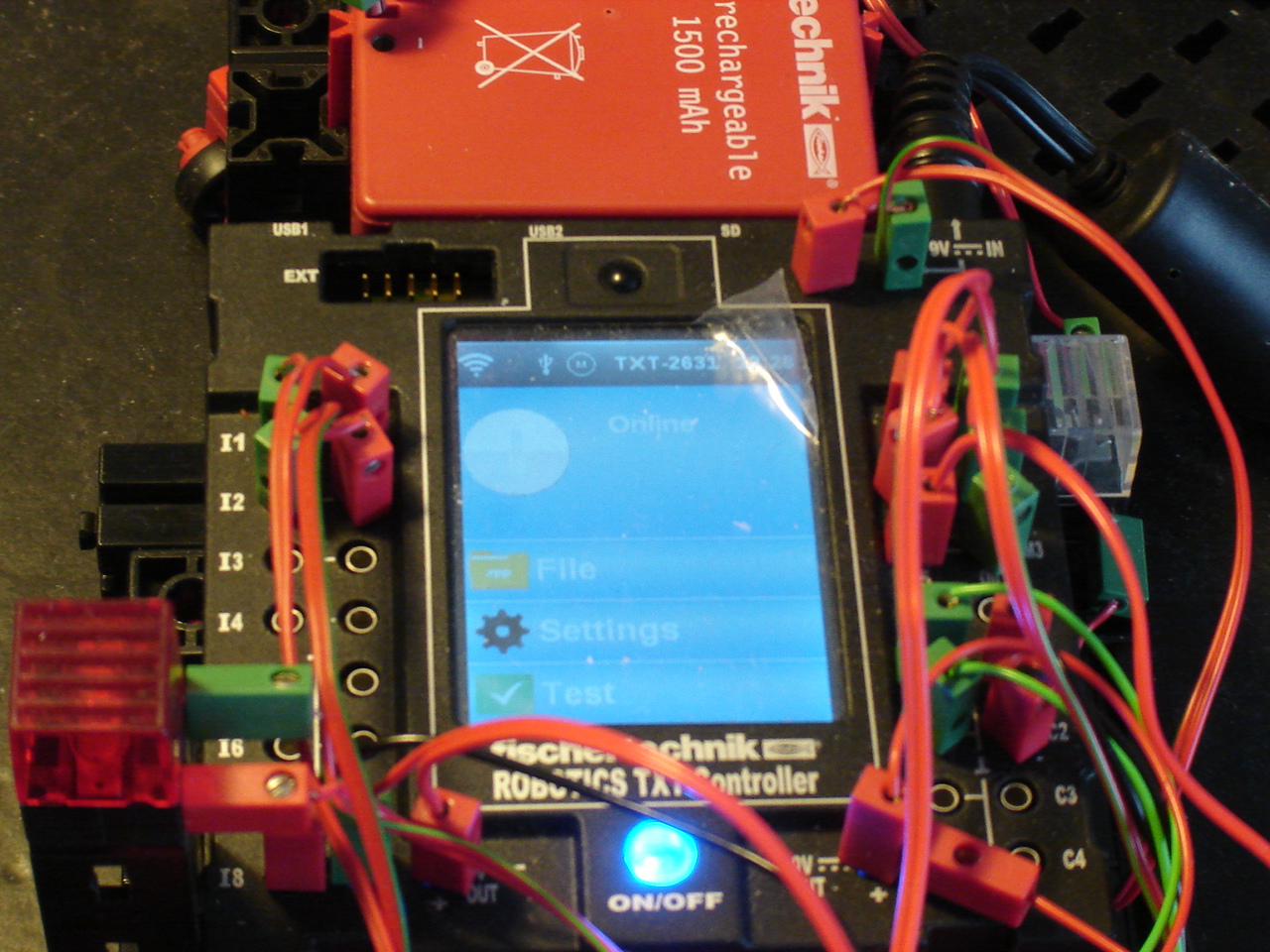
Discovery: To test if the touch and sonar works better via RoboPro, I wrote a similar program, see the screenshot/picture. Running this, didn't completely go as expected. See the video. However, it leaves enough to experiment with further. See also the picture with "Online" display while running Python.
I planned to see if this works better with C, but the power-off problem (again!) as shown in the video as well as the sudden disappearance of a loaded program from RAM (again!) has led to contacting and sending it to fischertechnik for diagnosis and hopefully either repair or replacement. Yuck.
Mydfir: The colour sensor so far has been attached to input A1. So what would happen if it was attached to input A2 ?
After quite some testing, it looks promising but only for this setting of light. See this video.
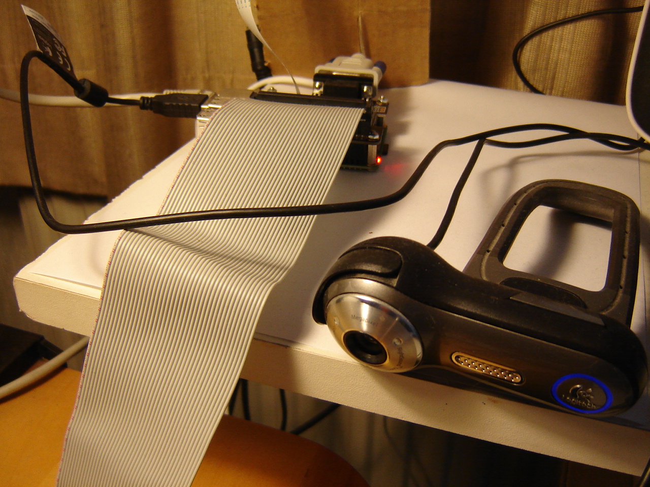
RPi: It would be nice to make a kind of split-screen screencast using video via the RPi. In my setup using VNC, the RPi cam is no option. So I try it by connecting the webcam to the USB and guvcview. Although as the picture shows, the webcam is obviously active (blue ring), the onscreen image from guvcview is black. Another solution is of course using OpenCV as I do on the BB. What I find then, is that the video window is very small. See the video.
13 November
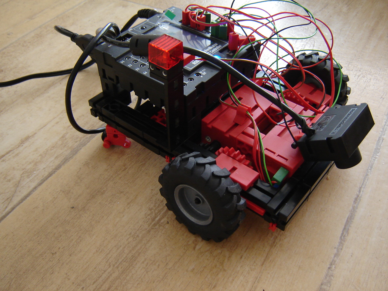
Mydfir: The riding robot is always a huge success on conventions. However, of the 3 sensors (sonar, line tracking and colour), the colour sensor seems to give wrong output (if any at all). After some testing, it turns out that the sensor does work, it just seems to be calibrated totally off. See this and this video for an attempt to calibration. Since these attempts are all with the same light source and brightness (cloudy daylight) and I don't have another colour sensor to compare with, there's more testing needed. So to be continued.
Mirft: Although the replacement of the bottom winches by clips worked, a problem turns out to be the chains: on some places they slip because they're apparently too long. Result is that the robot ends up on the floor after all. See this video for the experiments...
Hand: To make more clearly which switch activates which finger, I relocated the switches to the fingers. This took some experimenting. See this video. The compressor has a gear problem, but not sure how to solve it.
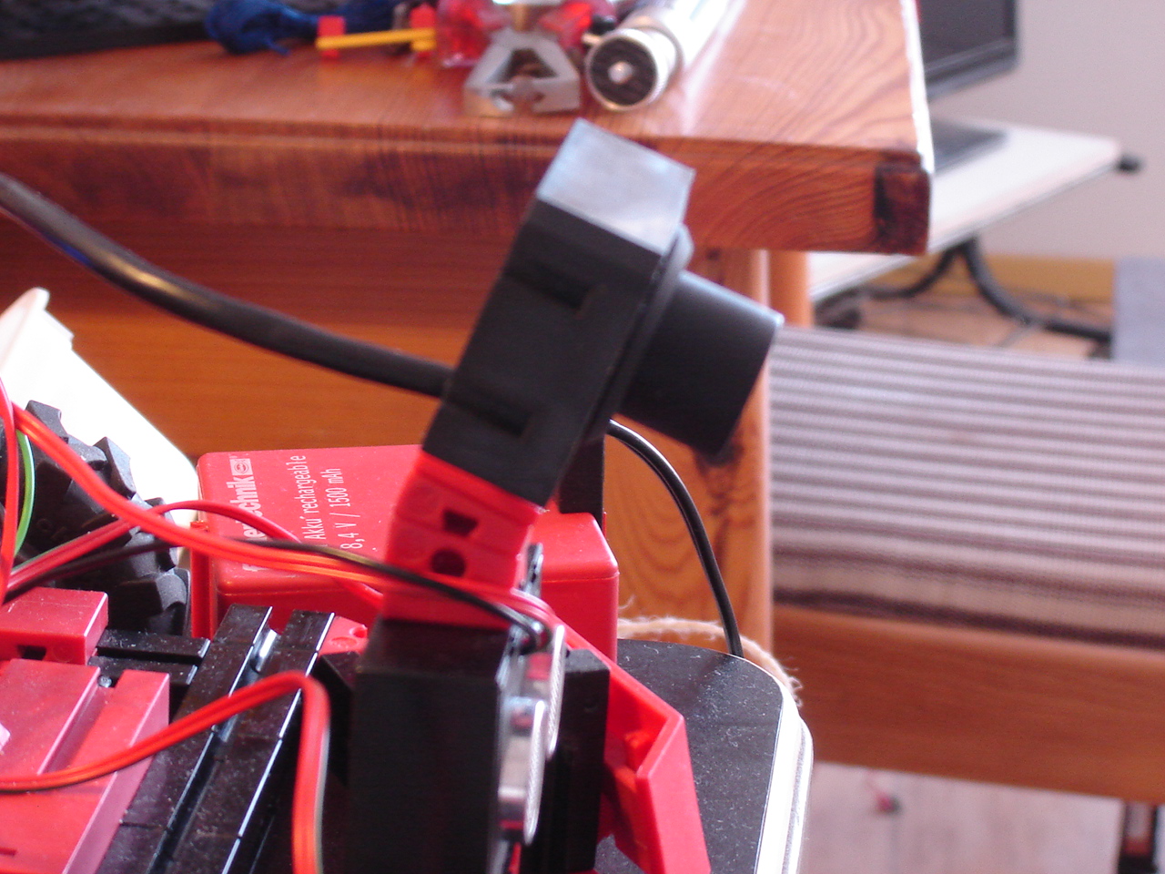
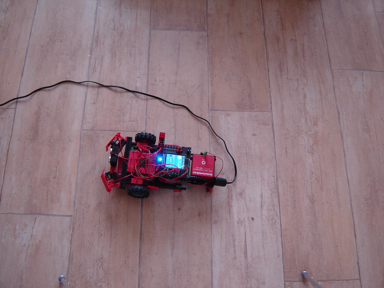
Discovery: More testing on the response from the sensors: is there are difference between 20 cm from the computer and 2 m away ? Because earlier tests showed that it didn't respond or very late to sensor input. As this screencast shows, it's still inconclusive. And the frequent returning all-zero response is also weird. The picture shows the Discovery motionless on the floor connected by the powercable: it's supported by a batterypack to keep the wheels off the floor.
RPi: Continuing with the 3-bits binary counter in C++, I change the inputstate check into 0. After this, the LEDs do something but it doesn't look like counting. Also, still nothing happens when I press the switch. But since the Python code does work, the suspicion comes that I may be playing with wrong GPIO port: 13 may not be 13. After a thorough check on the code that switches the LEDs, I find some errors: at some points the wrong LED is manipulated. I also change the switch time from 0.5 second to 2 seconds. After these corrections, I decide to run with inputstate still 0: the counter now works, but is not interactive. See this screencast.
BB: I wanted to do a C++ test with OpenCV, to see if I could get a better webcam result than with Python. However, with extremely little space left on the SD card, this is no option. So I may have to go for a 32 GB card, which the largest the BB can take.
6 November
Videos: Since all videos are available via Youtube, I removed all individual links and put links to playlists instead.
Discovery: After finding out that the TXT controller needs a minimum of 6V to run, I decide to test this: at 6.35V it's over. The next test is to see how long it takes for a full battery pack of 9.4V to unload: without the 2 motors running, it takes about 10 seconds per 0.01V. With the motors running, it takes some 4 seconds per 0.01V. So with 3000mV to unload and 4 seconds per 10mV = 4 x 300 = 1200 seconds = 20 minutes.
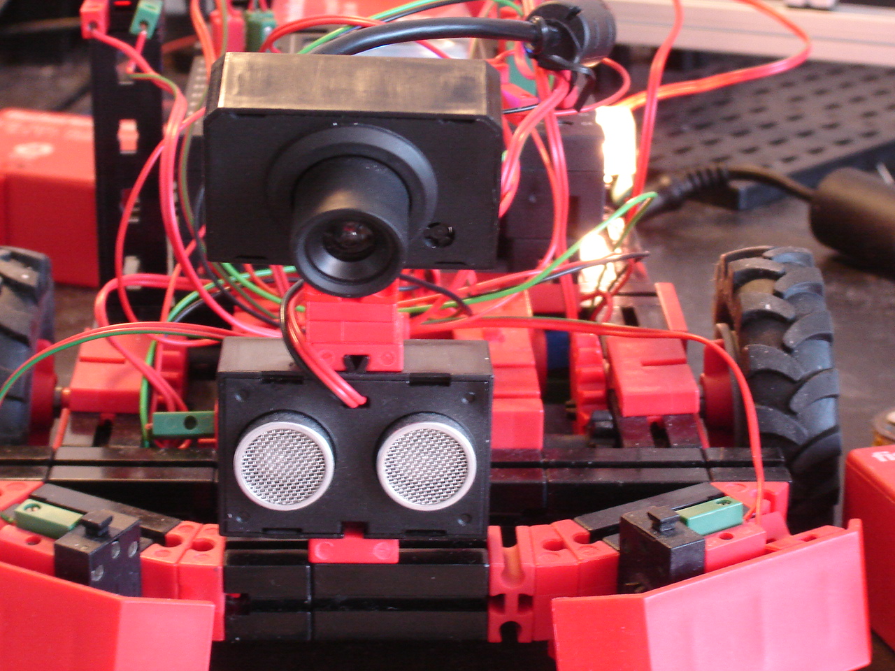
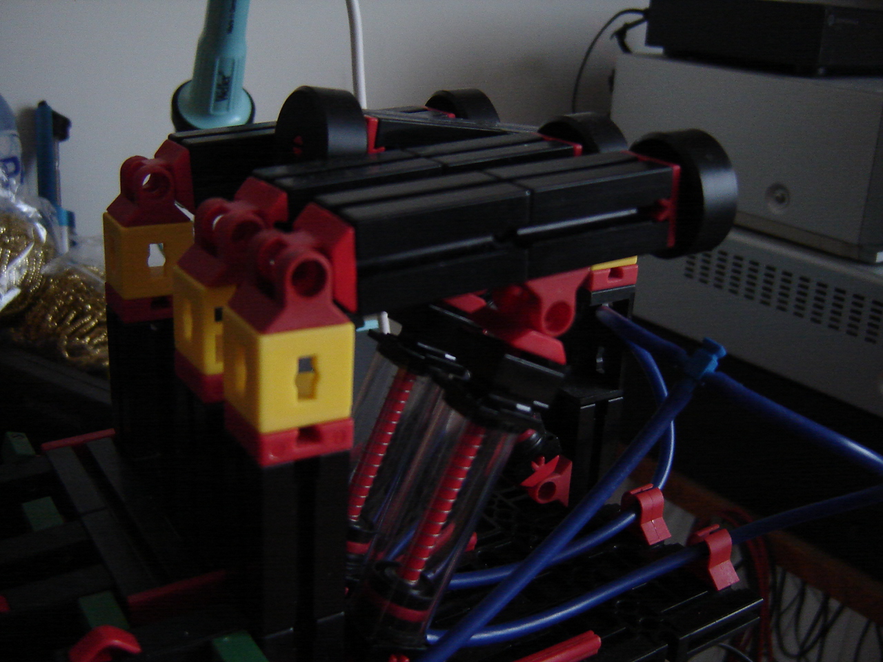
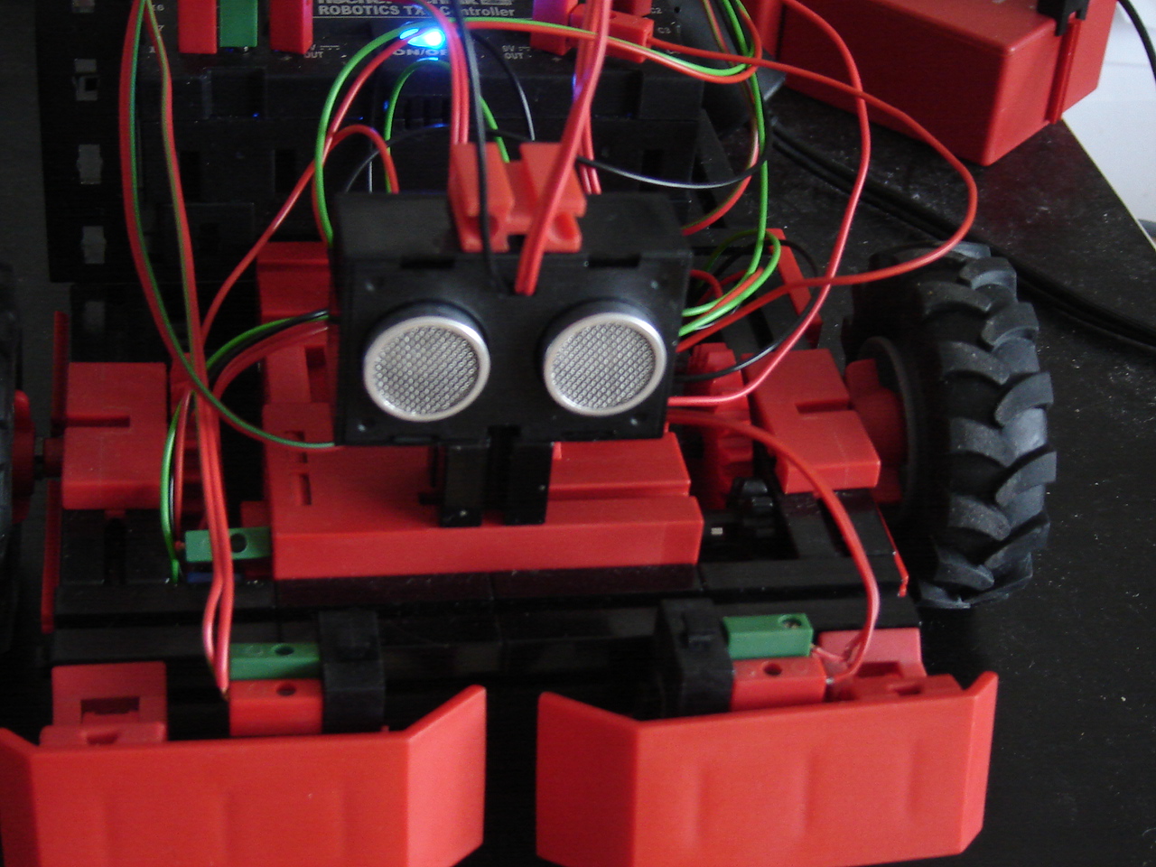
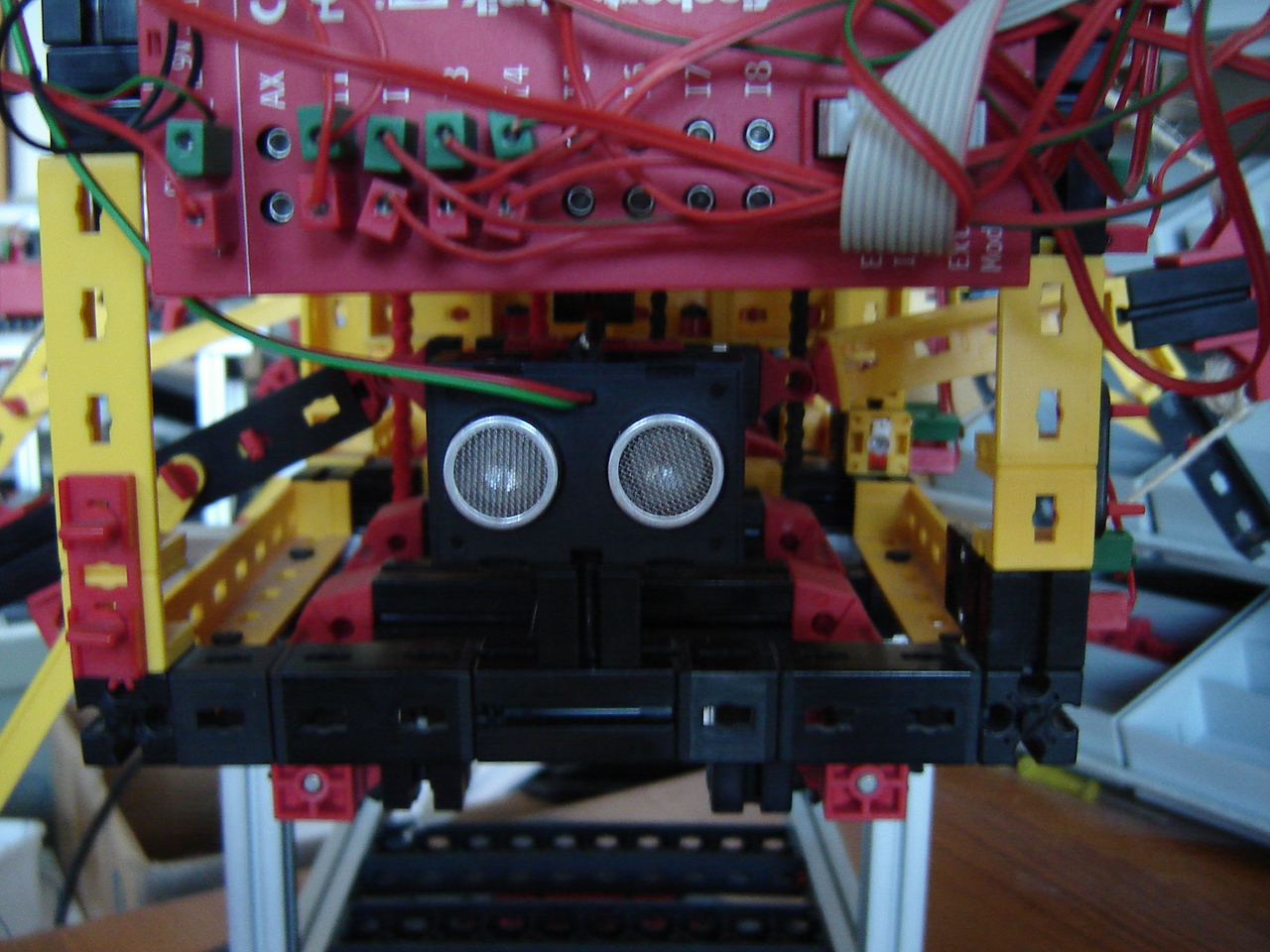
Next is of course the presence of the touch sensors (switches). With the sonar up front they're no use there.
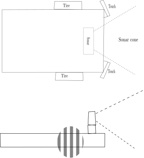
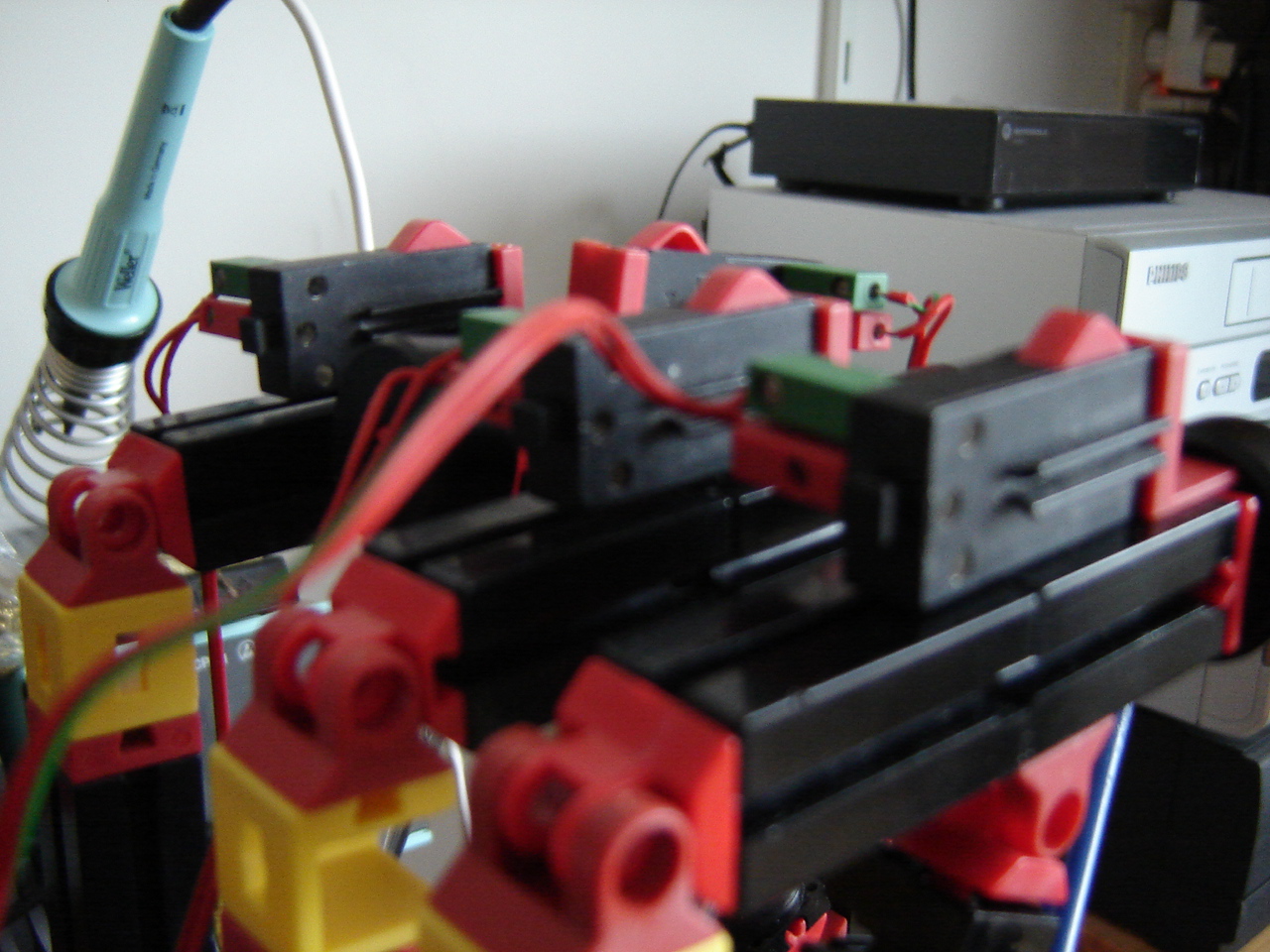
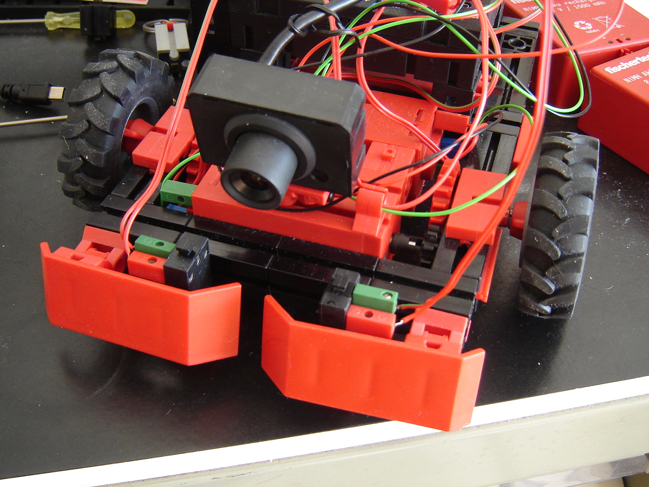
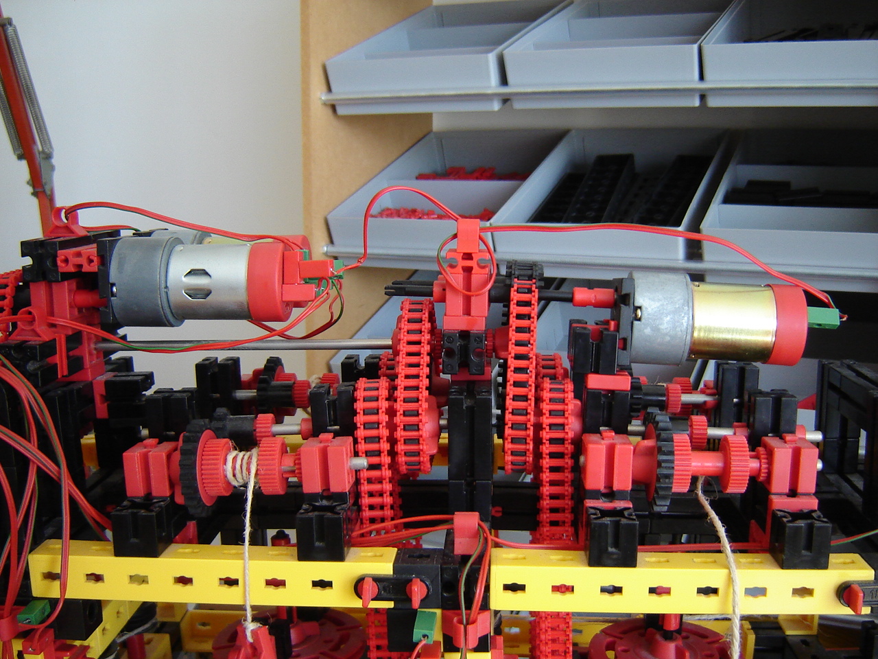
The above sketch shows the 3D sonar cone (of which in the sketch is assumed it has an outer bound of 30 degrees) with the touch sensors. However, some testing shows that the outer bound is merely 20 degrees. With such a smaller cone, the touch sensors can be used when they're relocated to the corners. So make this possible, I adapted/extended the frame of the Discovery. See picture 1. Testing shows that the sonar doesn't recognize any object placed on the riding surface. Lowering the sonar as shown in picture 2, shows no improvement on recognizing objects. See this video.
1:
 2:
2: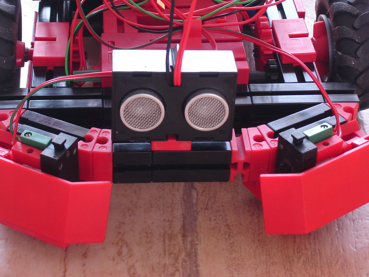
RPi: I continue my C++ experiments. After some minor changes, the code shows no positive results anymore, so I fall back to giving commands straight in the terminal. To my surprise echo "4" > /sys/class/gpio/export gives the error echo: write error: Device or resource busy. This means that my code does not unexport properly. This is proven when I do echo "4" > /sys/class/gpio/unexport and again echo "4" > /sys/class/gpio/export. This time there is no error, so it's necessary to review the code. It turns out there's a typo in the function sourcecode. But fixing this, doesn't solve the lack of positive results. Running the same algorithm in Python shows again that both the algorithm and the hardware simply work. See this screencast video.
Mirft: A continuing problem are the slipping winches and picture 1 shows a solution. However, with the use of this solution, the connection with the bottom side of the leg fails because of the direction. This is solved by reconstructing the leg, as shown in pictures 2 and 3. This video shows that it just might work.
1:
 2:
2: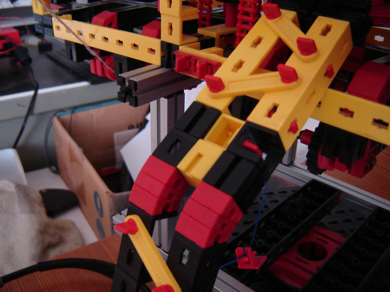 3:
3: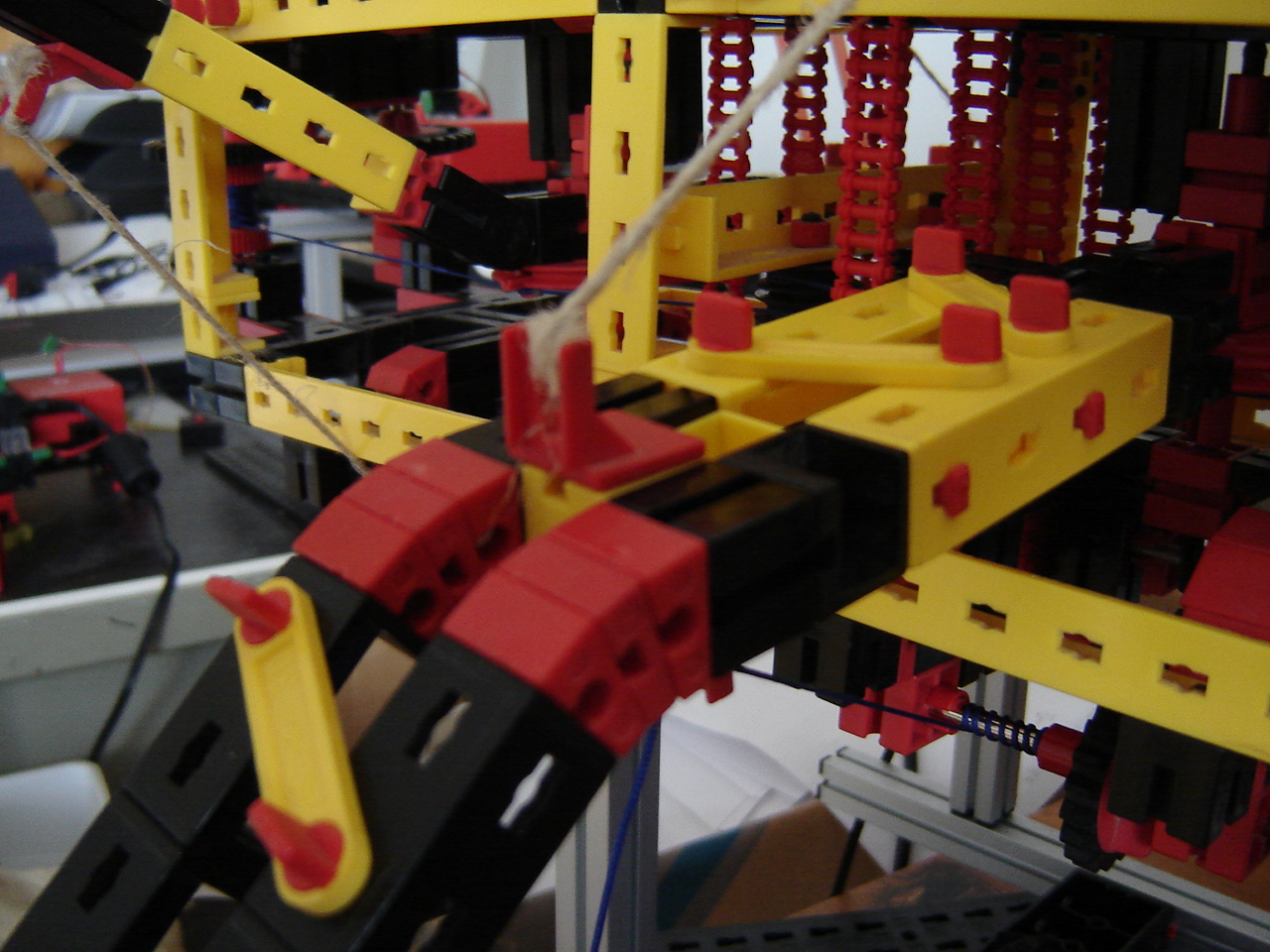
Hand: To make the hand a bit more realistic, I relocated the last added finger so now it has 3 fingers and a thumb. See the picture and this video.
30 October
RPi: As a challenge, I ported (i.e. translated) last week's interactive binary counter from Python into C++. To do this, I used this as an example. It shows a distinct difference: instead of using the pin numbering, the GPIO numbers are used: e.g. GPIO pin 7 is GPIO4. So this has to be changed in the code. Another issue is that in C++ a lot has to be defined first, so you create a header file and a source code file (or 2 or more). Compiling at first led to errors about the main function not found, but combined compilation g++ CPIOClass.cpp CPIOtest.cpp - o CPIOtest makes everything being compiled fine. Then, when running it, it reads the switch signal fine, then not, then again, then not. Ugh. So why does the Python code work fine and why does the C++ code work intermittently? See the screencast video.
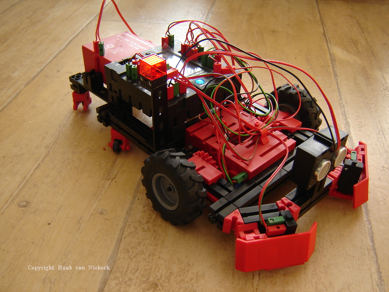
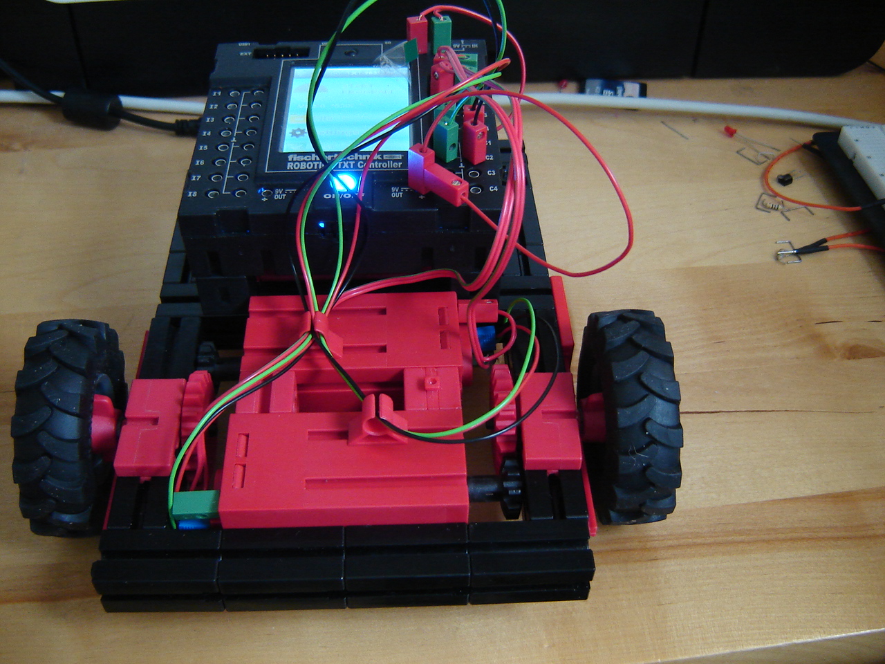
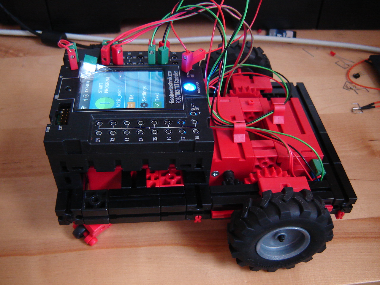
Discovery: I added a sonar to the TXT controller and thought I'd add the distance condition to the while. Since a logical OR either true or false, the condition becomes (left touch or right touch or (distance < 5)) == 0. So I'm measuring the distance up to 5 cm. With this done and working (see the video), I decided to extend the wheelbase to make changing the battery pack easier. Also, I added a light as battery pack indicator just like I have on Mydfir, the other driving robot. See the pictures.
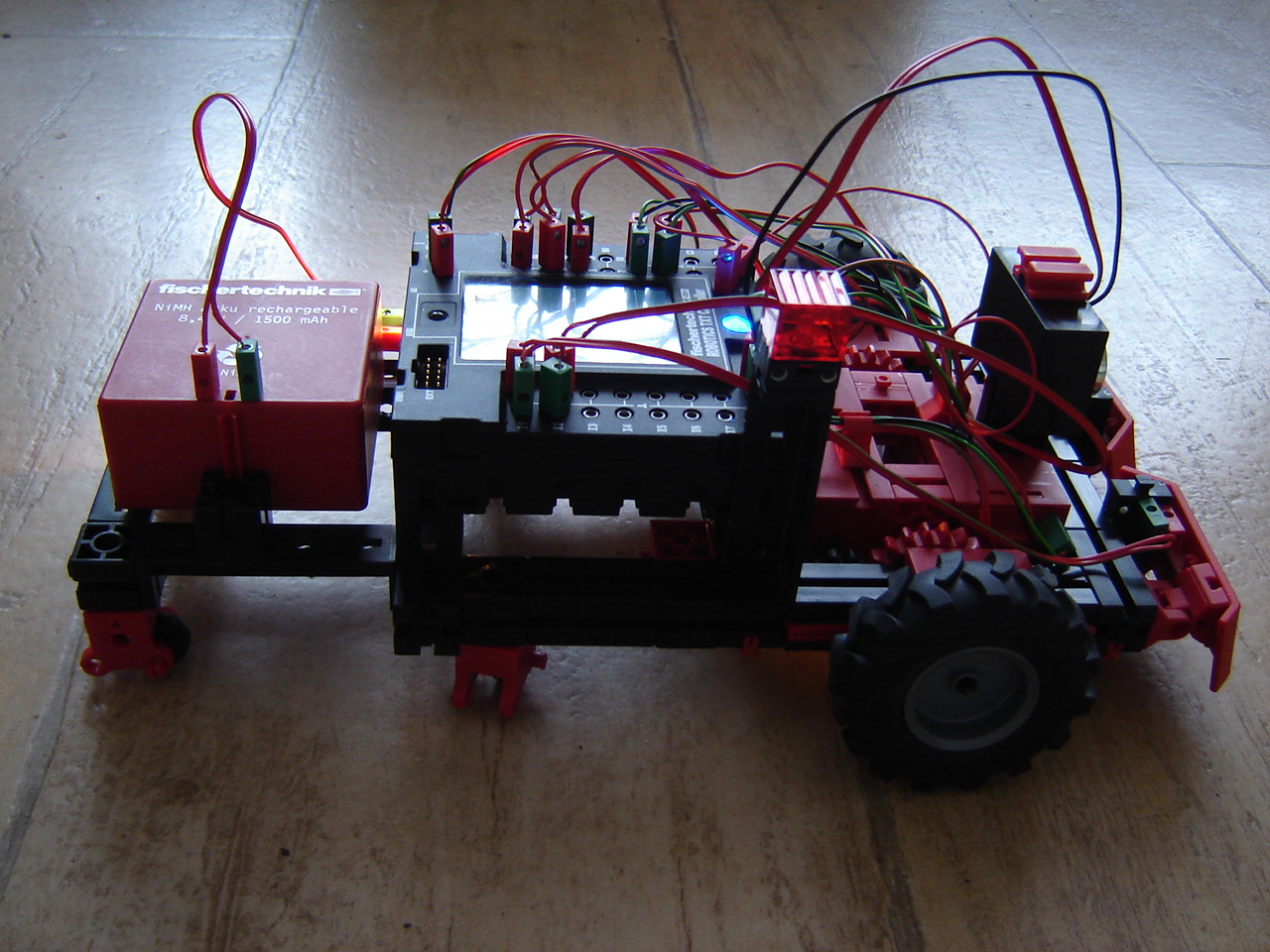
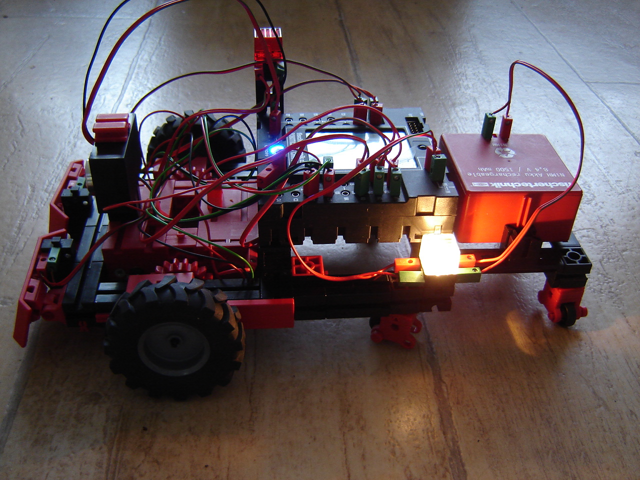
So for now, the Discovery has both tactile and sonar sensors as can be seen in this video, which shows that it doesn't always work as it is supposed to. Some remarks on the video:
- What I don't show in the video is that frequently the program just returns 0 for some reason. This is why the robot stands still for a while before it finally starts to run.
- The demo is recorded at 2 different times of day, hence the difference in lighting.
Hand: Since the hand is not really a hand yet, I built an arm to which the hand should be attached. This creates also the possibility to modify the hand so it's more like a biological hand: 1 finger/thumb across 3 fingers.
Mirft: After replacing 1 pair of hinges, the other 2 pairs needed replacement too together with broadening as many legs as possible, given the availability of parts. Along the way I found an existing construction mistake in the rear hip that had to be corrected. After switching 2 legs for the repeat of the floor experiment, it shows that the lower winches are a bottleneck. See the video.
23 October
Screencasts: In order to show the source code of my software better on video, I installed SimpleScreenRecorder. However, on the main laptop this couldn't be installed due to the fact that there was no package for Fedora 21 and I was unable to get it compiled. After checking out which distibution could replace Fedora (Fedora 22 and any Ubuntu didn't boot my laptop), the choice was Linux Mint 17.2 which booted straight away and is a LTS release based on Ubuntu Trusty. So for some time to come I'm safe.
Discovery: It turns out that the logical or (actually: inclusive or as opposed to exclusive or) works different in Python than I earlier understood. To get inclusive or you need to put both conditionals between brackets and put the comparison outside: (x1 or x2) == 0. See this video.
Hand: Replacing the duct-tape with a t-piece turns out to be a good idea. However, it still takes some time to compress enough air to let fingers 3 and 4 work fine. See the picture and this video.
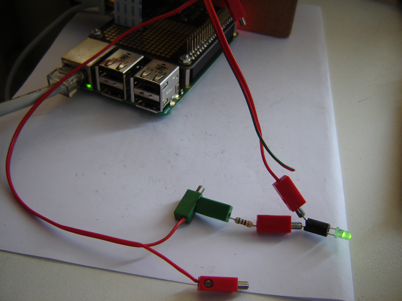
RPi: A 3-bits binary counter is nicer when it's interactive. So I added a switch according to schema 2 of this info using other pins. Important with the RPi is to use resistors, like I've shown in earlier schemas. The algorithm in Python results in a continuous binary counter as shown in this picture and this video and HD video (with RPi camera).
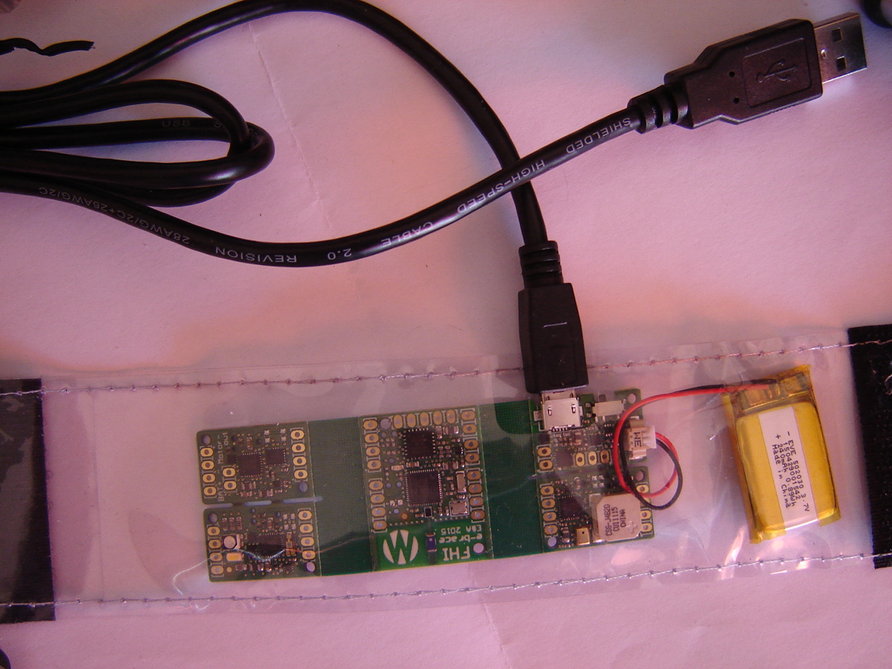
Arduino: After reinstalling the laptop, I took a new look at the software for an attempt to get the e-brace working. It appeared that, for some reason, the main directory had the wrong name which only was wrong in detail: Main-program instead of Main_program. This problem appears when I try to compile the program. After changing it, it compiles fine.
However, the movement program doesn't compile because of the errors 'MOVEMENT_OUT' was not declared in this scope and the same for ACC_CS. Then, trying the light program shows a similar problem: 'LED_x' was not declared in this scope, where x= R, G, B. Finally, the sound program gives 'SOUND_OUT' was not declared in this scope and the same for MIC_IN. So probably I'm missing something although I didn't change the software except for 1 correction (Gadget.h -> gadget.h) that made the main program compile and upload fine.
After downloading the software again from the original source, all problems but one are there. So I wonder how this ever worked in the first place. See this video.
16 October
Discovery: Using the algorithm from last week, I added 2 mini-switches with boards to the robot to detect obstacles and put the code into a while loop so it stops when some obstacle is hit. And as you can see in this video, the experiment is not going entirely as intended.
Arduino: Another attempt on programming the e-brace. After re-reading the manual and information the Arduino tutorialpage, I find that information on the e-brace is very scarce. So it is still not certain that the code I wrote works or not as shown in this video.
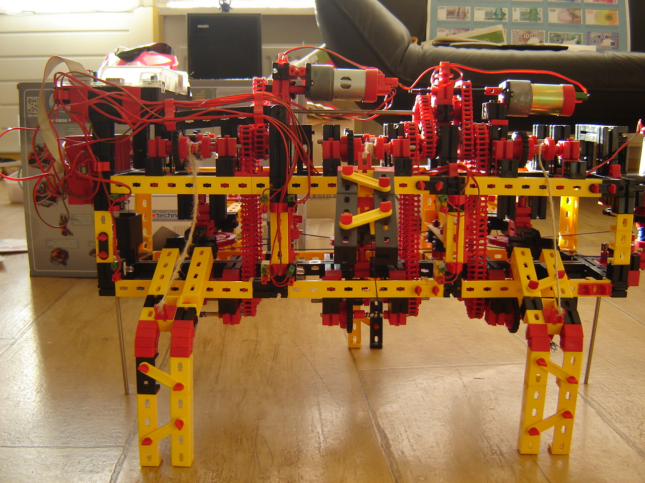
Mirft: A walking robot should be able to stand on its feet. A simple test shows that there are multiple problems with this idea when it comes to Mirft.
1: As expected the legs are too week: there is torsion when pressure is put on them. This can be solved by either replacing them with aluminum or reinforcing them. Another part of the solution is to replace the hip hinges as shown in these pictures.
Another stabilization improvement would be to broaden a leg, as shown in these pictures.
2: Also as expected, the current strings are made of rope and should maybe replaced by stronger material such as nylon.
3: Not as obvious is the slipping of the vertical winches.
As this video shows, putting the weight of the robot on the legs, isn't working good enough yet.
RPi: After the walking LEDs, I decided to make a binary counter. Using 3 LEDs, it counts to binary 111 or decimal 7 as shown in this video. Using the RPi camera, it shows the counter as well, but since the video is made from the RPi side, the Most Significant Bit is on the righthand side. Technically, both are valid and their use depend on the convention you use.
9 October
Videos: I created 3 more compilation videos. This time from the TeamBuildingDay in 2008: first, second, and third challenge.
Discovery: Although the controller is running Linux, I find that e.g. the vi editor is not fully implemented: the u command (undo last action) is missing. Apart from that this, this and this video show some real and continuing experiments with Python. Check pwm for the use of the light.
Arduino: As an intermezzo, I went back to the Arduino e-brace I last tried around 30 July and made a first and second video of a live-experiment with programming with C.
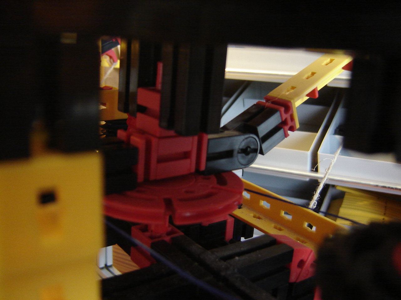
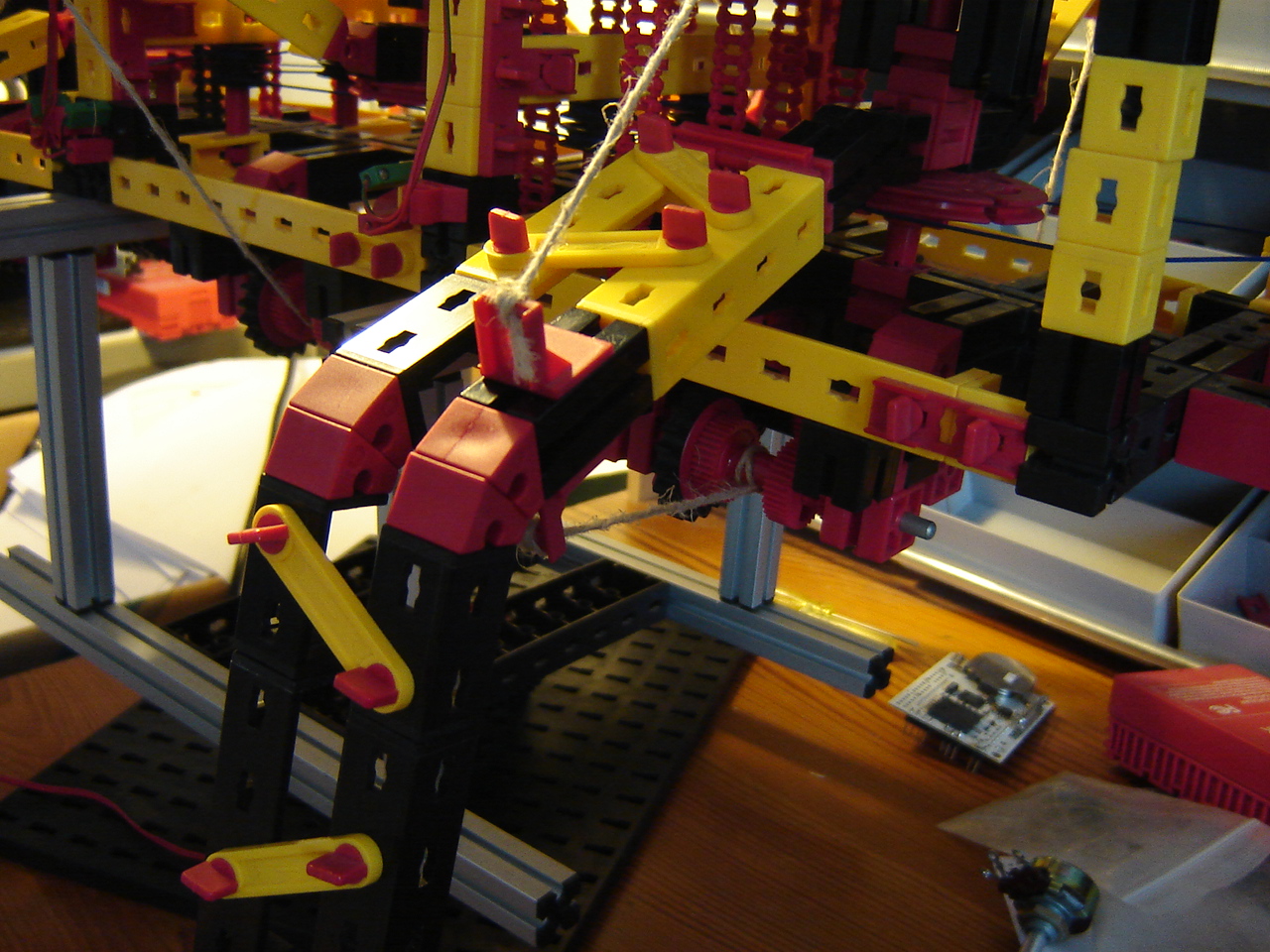
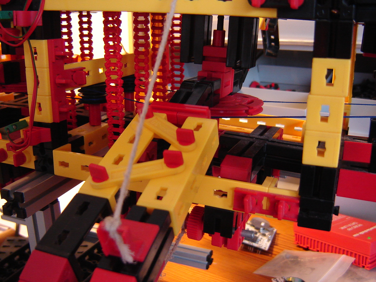
Mirft: When trying to solve the problem of horizontal movement boundary, an idea would be to use a lense-lamp vertically. This brings another problem: where to put it so it doesn't interfere with the string and leg. So in these sketches 2 options are shown. Neither is really good because option 1 interferes with the leg in top position and option 2 with the string.
1:
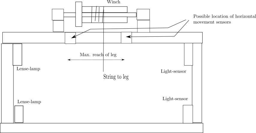 2:
2: 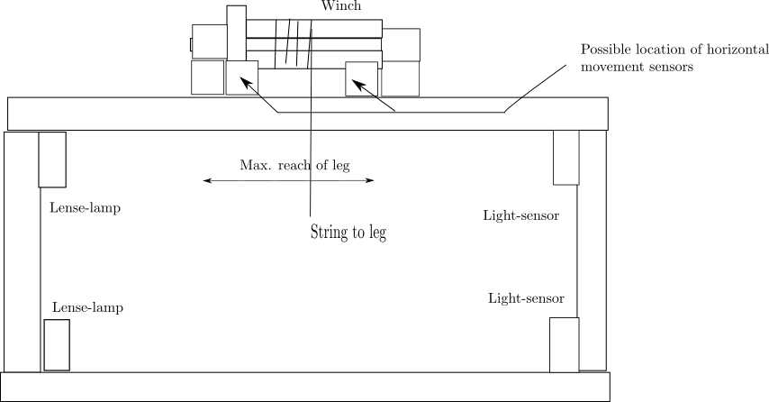
2 October
Videos: I created some compilation videos which can be found in the playlists on Youtube.
Mirft: At the ft convention in Dreieich, someone gave me a sonar sensor which is suitable for the ft RoboInterface. I put it at the front of the robot and connected it to the D2 input of the controller.
A quick test using the Diagnose software reveals it's working nice and obviously it will function as an object detector. In my own software, I will have to enable the sonar by using bEnableDist=1, the same way I did for the riding robot. The main code starts now with while t.GetD2 > 10 so the object has to be further away than 10 cm for the robot to keep moving. See also this video.
Discovery: After trying to get things working via ROBOPro, it's time to get back to Linux and make a start with Python: the ftrobopy library and the Python_for_TXT library which were made available in this community thread. After following the instructions, it shows that the first example works nicely, as show in this video.
25 September
Hand: Recently I decided to use the 4th cylinder and connect it to the same valve as is used for the 3rd. However, because I lack a 4th t-piece to connect the air-tubes, I tried to use ordinary adhesive tape to couple them. For a short while it worked. Time for another solution: using duct-tape
as also shown in this video.
18 September
BB: After using the BB in combination with the webcam a couple of times, I realized I had not demonstrated how that actually works. So I made this video.
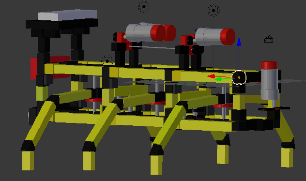
Mirft: I noticed that the 3D model created with Blender was not up-to-date anymore, so I added the 3rd motor.
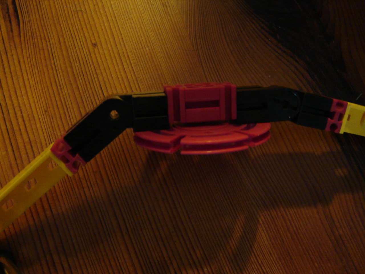
Then, for the real "thing", a way to fix the connection of the horizontal string to the hop wheel is using a clove hitch on a spring cam as shown in this picture.

The problem with this is that it is rather hard to place a clover hitch at the exact positions on the string but with some perseverance it was done. Another problem is that each one can only be located at the bottom-side of the hip wheel, so tests will reveal if this will work with the guide wheels. This video shows some first tests.
Hand: After some remarks, I appended some "ends" to the fingers. I also rerouted a few tubes to the cylinders, so it doesn't look as wild and unorganised. I also made an overview video, but with a partly failed demo because of an airleak.
11 September
RPi: Continuing with the walking LED, I find 2 causes for the 3rd LED issues. The 1st cause: the programmed pin and the physical pin don't match: 29 vs. 27. Once that's corrected, the 3rd LED burns throughout the run of the program. This is solved by setting pin 29 to "False" before the actual algorithm begins, so there's no voltage on it. Then when the LED is supposed to burn, set pin 29 to "True", and the walking LEDs work. Sigh.
Then it's also nice to have them "walk back" which should just be a matter of extending the algorithm. Unfortunately, the red LED goes on and off until the wire to GPIO input pin 32 is connected. This wire should give the signal for the turn-around. Replacing the red by a green LED (which burns brighter) doesn't resolve the issue, but recounting the pins does: the wire was accidentally connected to pin 34 (ground). So these are pictures of the full circuit with 3 green LEDs: 1) normal camera 2) webcam (cropped/edited with Gimp). See also this video, RPi video (HD) and webcam video (which again looks like speed-up).
1)
 2)
2) 
Mirft: Because of the problems caused by the rope for the horizontal mechanics, I replaced it by the blue nylon string that is part of a fischertechnik box. See the pictures of both mechanical ends.
A test shows that it now takes 8 seconds for a leg to move between its extreme positions. However, since I can't rely on the position a leg is in, I still have to find an extreme position detection method. After a small code change by putting the if statements a while loop, I find 2 issues:
- the horizontal mechanics have to be looked after. The winches slip and loose tension as this video shows.
- the vertical mechanics stop too soon. Result is that a leg's extreme down position isn't reached as this video shows.
4 September
Videos: All TeamBuildingDay videos have been put together now. See the video page.
Youtube: All videos are grouped in playlists now which makes searching a lot easier.
Picasa: I found that some picture-links on the Video page were no longer working and corrected them. So all links should work again.
RPi: A simpler setup of an experiment is to put a series of LEDs like this: the 1st LED is put "1", then "0". The "1" makes the 2nd LED going "1" and "0" and finally the 3rd LED. The schema shows a simplified setup.
However, during the experiment, GPIO pin 7 goes wrong and starts giving a constant 1.8 V which leads to a constant low burning of the 1st LED as shown in this video. However, using gpiotest from pigpio shows that only pin 10 (gpio 15: UART RxD) fails. After reconnecting the wires up to the 2nd LED, this video shows that the program and setup actually do work.
Mirft: The problem with the lights turns out to be both programming and electric wiring. A few of the remaining problems: slipping of the mechanical wiring, horizontal detection. This video explains (at least a piece of) the way the horizontal movement should work.
Hand: With 1 spring cylinder remaining, I wanted to add a 4th finger to the hand. Problem is that I only have 3 valves and 2 T-pieces for the air, all of which are already in use. So I decided to use adhesive tape and put 3 tubes together: 1 from the valve, 1 to finger 3 and 1 to finger 4.
You can see the result in this video.
28 August:
Videos: All TeamBuildingDay 2008 and 2010 challenge videos have been combined per challenge and contestant. See the video page. The rest will be available soon.
YouTube: Created playlists so videos can be found much easier. More to come.
Discovery: Further testing seem to point at a firewall problem with an time-window of only 5 seconds. nmap shows the needed port 65001 is closed on 192.168.8.100 which is the WiFi connection to the TXT. With ufw I open the firewall for port 65001, and start a test via ssh to record what actually happens during program execution with this as start of the output:
-------
01: TxtControl Start
/dev/ttyO2 65000 131 dump.txt
debugflag 1 active: data exchange rates (camera, I/O, transfer)
debugflag 2 active: camera sensor results
debugflag 128 active: enumerate supported camera modes
InitSerialToMot - 1
OpenSerialPortToMot - 1
KeLibTxt: TxtControlLibInit
WLAN-ID: ft-txt_2631
-------
but testing shows no improvement.
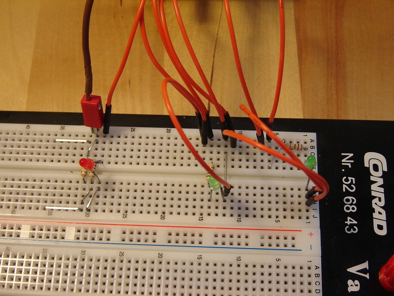
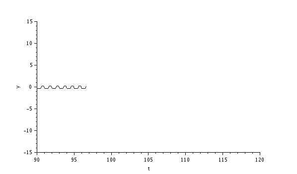
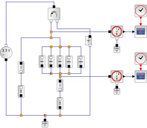
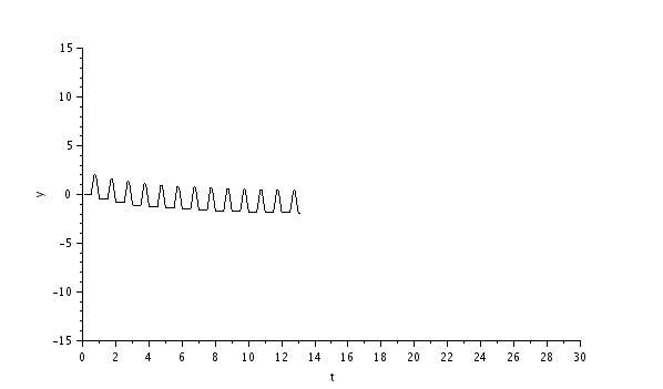
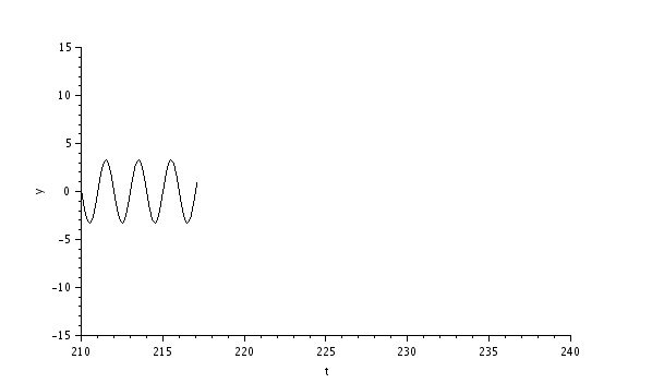
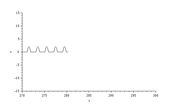
RPi: Another option is to use multiple inductors in series in an RL circuit, thus adding up the inductance. So to have more inductors, I extend the electrodes of another one I desoldered earlier and create this circuit and outputs: screenshot, image from oscilloscope1(upper in schema) and oscilloscope2 (lower in schema).
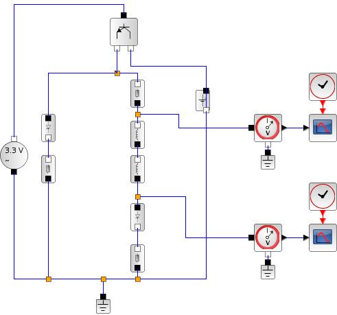
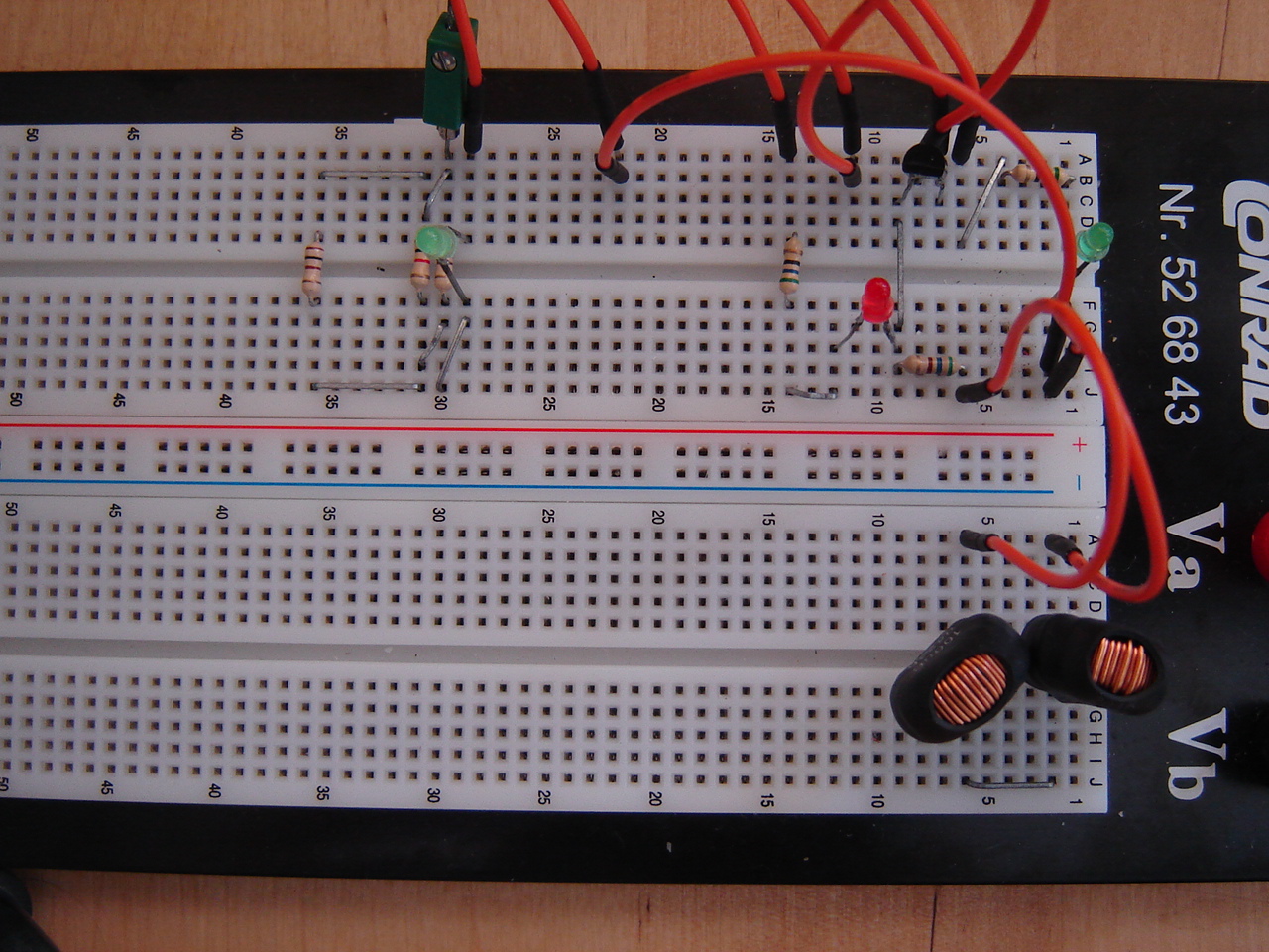

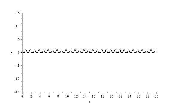
This result shows that although the recorded input to the GPIO from the inductors isn't alternating the way I expected, the control LED is constant burning while running the code. Another result is that the LED behind the inductors doesn't burn. This appears to be a improper connection, and after reseating the resistor in the RL circuit, the result is this:
Also, a change of code (adding time.sleep of 0.5 second) for the control LED makes it alternating. The change is necessary since this LED is directly controlled by the GPIO, not by the transistor. So the end-result of this experiment can be seen in this video and this video (RPi camera in HD).
Mirft: Getting back after focusing on the Discovery, there are some sensor issues such as lamps that don't burn when they should, receivers that report "on" when the lamps are "off". Since I'm using the RF DataLink for remote communication, I remove it for testing and use a wired USB link. This seems a bit better, and after checking some wires it improves even more for the lamps. However, the sensors still report wrong data, and the motors don't run. Time for troubleshooting.
21 August:
Discovery: The TXT will be left out of any ROS experiment because, although it runs Linux, it doesn't run a supported Linux version.
On colour detection: in this video I'm using a ROBOPro example program that acts on the colour red which doesn't work either. This convinces me the problem is not with my software. Running wireshark might show if it has something to do with the firewall or not.
RPi: Experimenting on ROS for RPi starts with a bit of research that takes me here. If I want to install ROS, I have to build it manually.
Continuing with the RLC circuit, I want to have a 3rd LED indicate that the RPi detects via the GPIO that the circuit works.
So I place a jumpwire from the green LED at the end of the RLC circuit to the GPIO input pin and see if it is detected by
---
print GPIO.input(22)
---
it prints 0, so it isn't detected. Simple explanation: the voltage at that point is quite low. Then I relocate the jumpwire end from the green LED to the parallel C part (which is the end of the circuit) and the input on pin 22 shows 1. However, the 3rd LED doesn't burn. Although this is unlikely, reason can be that the 100 Ohm value of the resistor is too high. This can be solved by resistance division: put multiple resistors parallel and the inverse total resistance 1/Rt = 1/R1 + 1/R2 + .... So in case of 2 resistors of 100 Ohm, 1/Rt = 1/100 + 1/100 = 1/50, making Rt = 50 Ohm. Despite this solution, the 3rd LED doesn't burn the way I expect it to do.
Time to do some tests:
1) Putting the 3rd LED parallel to the red LED proves that the 3rd LED works fine.
2) Measuring the voltage on GPIO pin 29 (used as source for the 3rd LED) shows a permanent 1.69V, which is wrong.
3) Measuring the voltage over the green LED after the RLC, it shows faint burning at 1.69V, so the 3rd LED should do the same.
4) In enough darkness, the 3rd LED does show a constant very faint burning, merely a glow which is easy to miss.
Since pin 36 can be in- and output as well, a solution can be a change from output pin 29 to 36. After changing the code accordingly, the 3rd LED burns very brightly as this video and this video (RPi camera) shows. So what's wrong with pin 29 ?!
BB: Searching for software that can be uninstalled leads to the discovery that PyAudio actually is installed. However, the printing of errors on screen
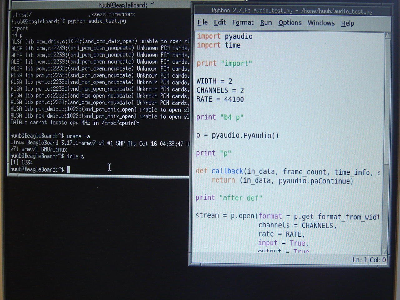
reveals that it probably won't work as easy. The last line returns "unable to open slave". Another "FATAL" error is "cannot locate cpu MHz in /proc/cpuinfo", although according to several forums this is a kernel issue. So I guess audio on the BB won't work for now. Because Ubuntu runs on the BB, ROS should be installed easily.
ROS: Apart from the embedded boards, the laptop runs Fedora Linux, which is unsupported by ROS. So if I want to use ROS on it, I would have to replace it by Ubuntu and for some weird reason Ubuntu/Xubuntu/Lubuntu 14.04 doesn't even boot my laptop. I decide to install ROS on an ordinary pc with Lubuntu (which goes smooth) and will see from there.
14 August:
Early videos: I realized that the videos links I gave in the beginning of the blog still lead to Picasa. Of course all these videos are on Youtube now and accessible via the video page. I will not change the links in the blog to Youtube, unless I'm asked to.
Discovery: With the camera live-feed on the tablet, I took these images of the lines that should be followed. According to the developer, these should be no problem in being detected. The last 2 image are made with different light intensity.


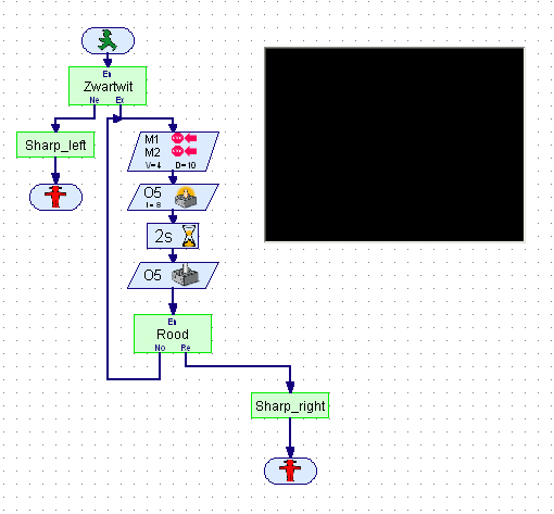
Then another problem starts being quite persistent. Previously there was no problem using the WiFi connection from ROBOPro. However, now I keep getting the message that it can't connect to the TXT. Testing this from a terminal with ssh, there's no problem getting on the TXT. Also, getting camera live-feed on the tablet is no problem. Eventually I'm able to make this video. In the flowchart you can see where the short 2 seconds pause is (the lamp burns) and which at times takes a lot longer (without the lamp burning) probably due to communication issues.
Since Bluetooth is another option to communicate with the TXT, I use a Bluetooth dongle which finds the TXT nicely and pairs with it. However, after several attempts trying to set up communication between ROBOPro and the TXT, there is no result. Probably because it a USB dongle and wine doesn't know how to handle USB.
The next attempt is to load the test program into the RAM of the TXT via USB. This at least takes out the flaky WiFi connection between the TXT and the laptop. Remarkable is that other WiFi connections with the laptop go fine. Unfortunately, this video shows that this doesn't solve the problem either. So if the problem isn't either software or the camera, it could be the TXT itself.
BB: Since the use of the webcam has only delivered speed-up videos, apart from good pictures, a better idea is to experiment with ROS, likely in combination with the RPi and laptop. Since ROS enables communication between devices via messaging (within ROS also known as topics), basically all my controllers can be interconnected. Only issue is that I'm using a 16 GB SD card with 97% used, so I can't install ROS right now. Maximum SD card capacity for the BB is 32 GB.
RPi: Another component is the inductor, with symbol L. Building on the circuit from 7 August, and looking at example RLC circuits, this is the most interesting experiment yet. The letters are in sequence from the voltage source, so the resistor comes first. This also means I have to redesign the circuit: a resistor to begin with and one to end with (a protection between the GPIO and the LED). In between the resistors will be the inductor and capacitors.
From old PCBs I get inductors of 4.7µH (H = Henry) and 100µH. Using the 100µH, and simulating an RLC circuit with a resistor of 2200 Ohm, the signal after the capacitors does get stronger as expected, but the maximum value stays at 0.25V and with 0.25V a LED will not burn.
Increasing the resistor to 10k Ohm doesn't improve the result, as the pictures show: actual setup (1),schematics (2), upper oscilloscope(3), lower oscilloscope (4). With a 56 Ohm resistor, the 2nd oscilloscope graph (5) which ends in a simulation solving error after 18 seconds.
The results are as a series RLC circuit: as the resistance is higher, the end result is over damped. With a low resistance it should result in under damped (so the green led after the capacitors should burn at start) but the simulation ends in error. As you can see in this video (normal camera) and this video (RPi camera), using a 56 Ohm resistor, it does work with the green LED in the RLC circuit burning rather faintly. This again shows that a simulation is not always showing the same result as the real thing.
1
 2
2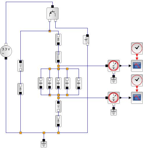 3:
3: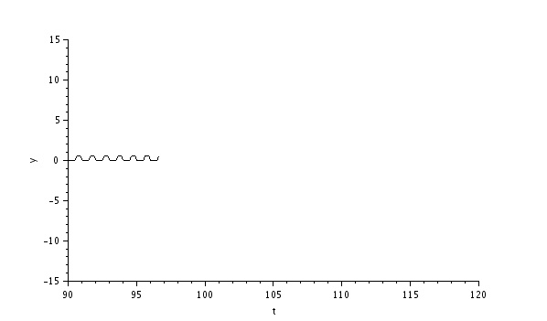
4:
 5:
5: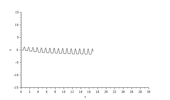
7 August:
Fix to 30 July blog: pictures.
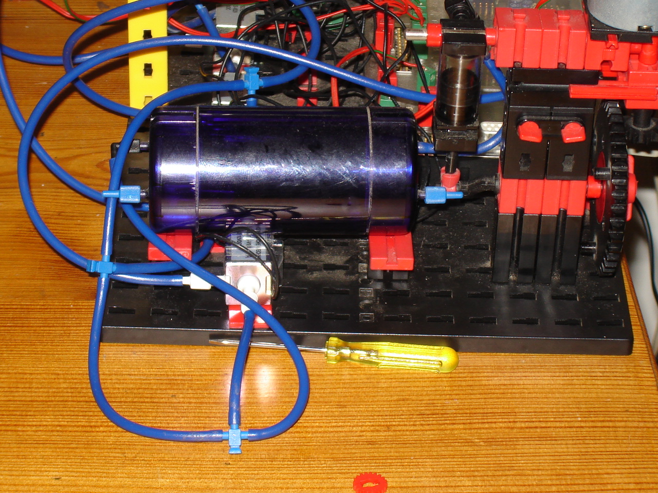
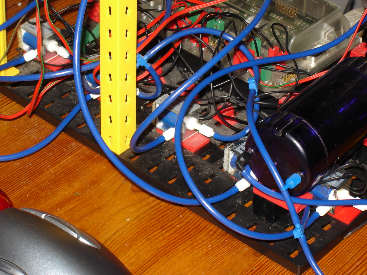
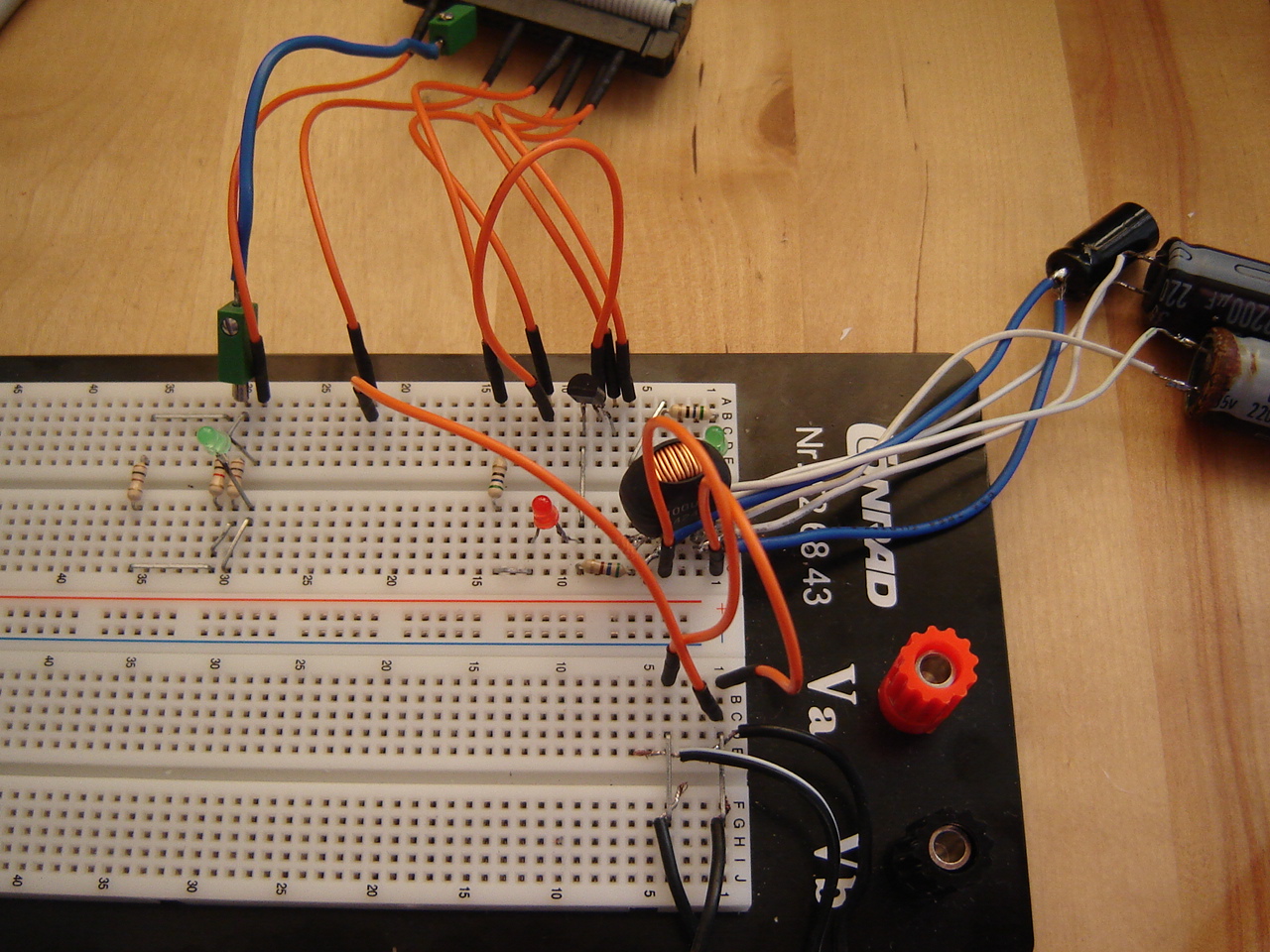
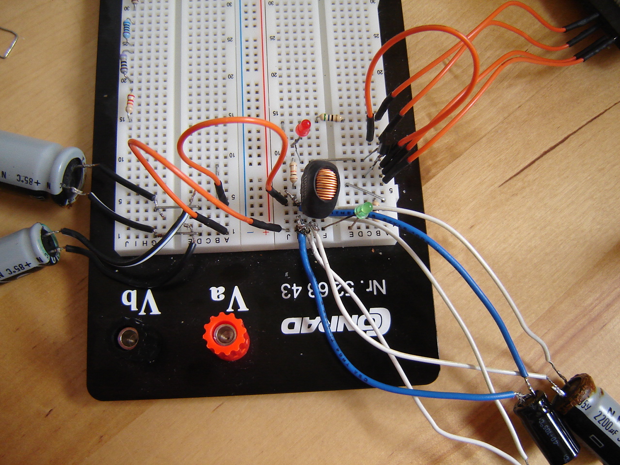
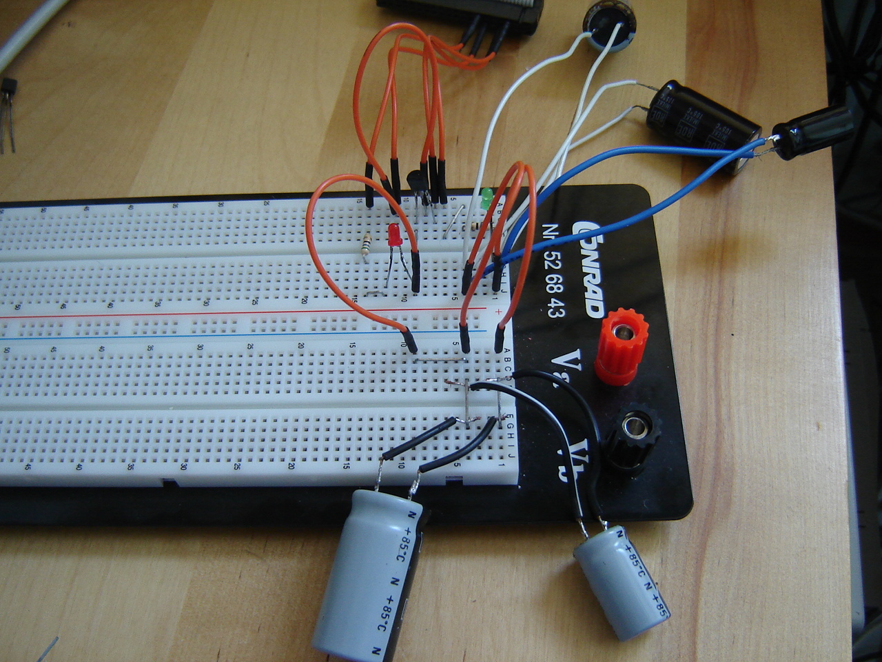
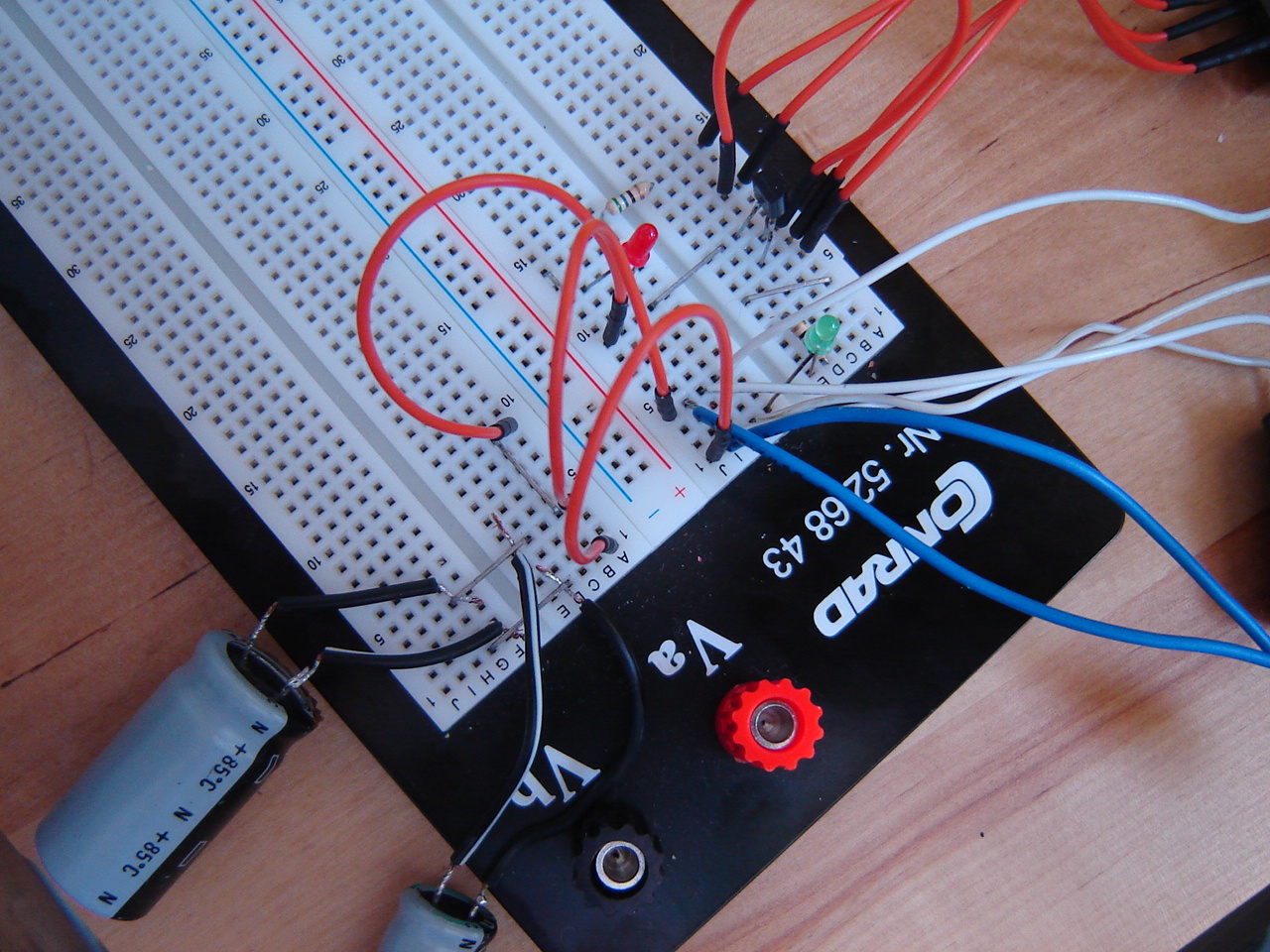
RPi: A component I didn't use yet, is the capacitor. So it's time to experiment with this one. The plan was to have a LED before as well as after the capacitor. The first simulations showed there was no voltage after the capacitor, which was just 100pF (picoFarad). To solve this, the voltage source has to be a multitude of 3.3V. Since this can't be realized with the RPi, the solution is to increase the capacity and use electrolytic capacitors of at least 1000 µF and put them in parallel. That way it should work according to the simulation: the LED on the negative side of the capacitors shows a dimming effect as can be seen in the simulation and video. At the first run, the green LED burns quite brightly, and during subsequent runs the LED quickly dims until it no longer burns. After that, you will have to wait a while before starting again because the capacitors need to discharge first, which happens slowly.
As you can see in the pictures, I had to extend the electrodes of the capacitors with wires because they were too short for the experiment. Also, I had to extend the working space for the experiment due to the number and volume of the capacitors. To create the extension I used jumpwires and I used staples as aides to connect the capacitors in parallel. The staples were necessary because the extended electrodes would not stick in the breadboard. The total used capacity = 6800µF + 3x2200µF + 1000µF = 14400µF = 14.4mF.
Discovery: After making contact with the developer of ROBOPro, it turns out that wine doesn't support USB. So that will be the prime reason that the camera doesn't work in ROBOPro when attached via USB. However, I use mainly WiFi, which should work. It turns out that the camera only responds to a colour when it doesn't fill the complete image. Another problem may be that the lsusb command on the TXT doesn't list the camera.
After a few small adjustments to the testcode, and testing with black/red line-colour recognition it first seems to work better but either colour still isn't recognized. To be continued again..
30 July:
Youtube: I've put the last old convention videos from Hoofddorp (2011) and Vlissingen (2008) online that were on Picasa only. Since Picasa still shows the error "invalid parameters" when playing videos I will remove them. The pictures will remain on Picasa.
RPi: The next experiment is to replace the resistor by a potentiometer or potmeter.
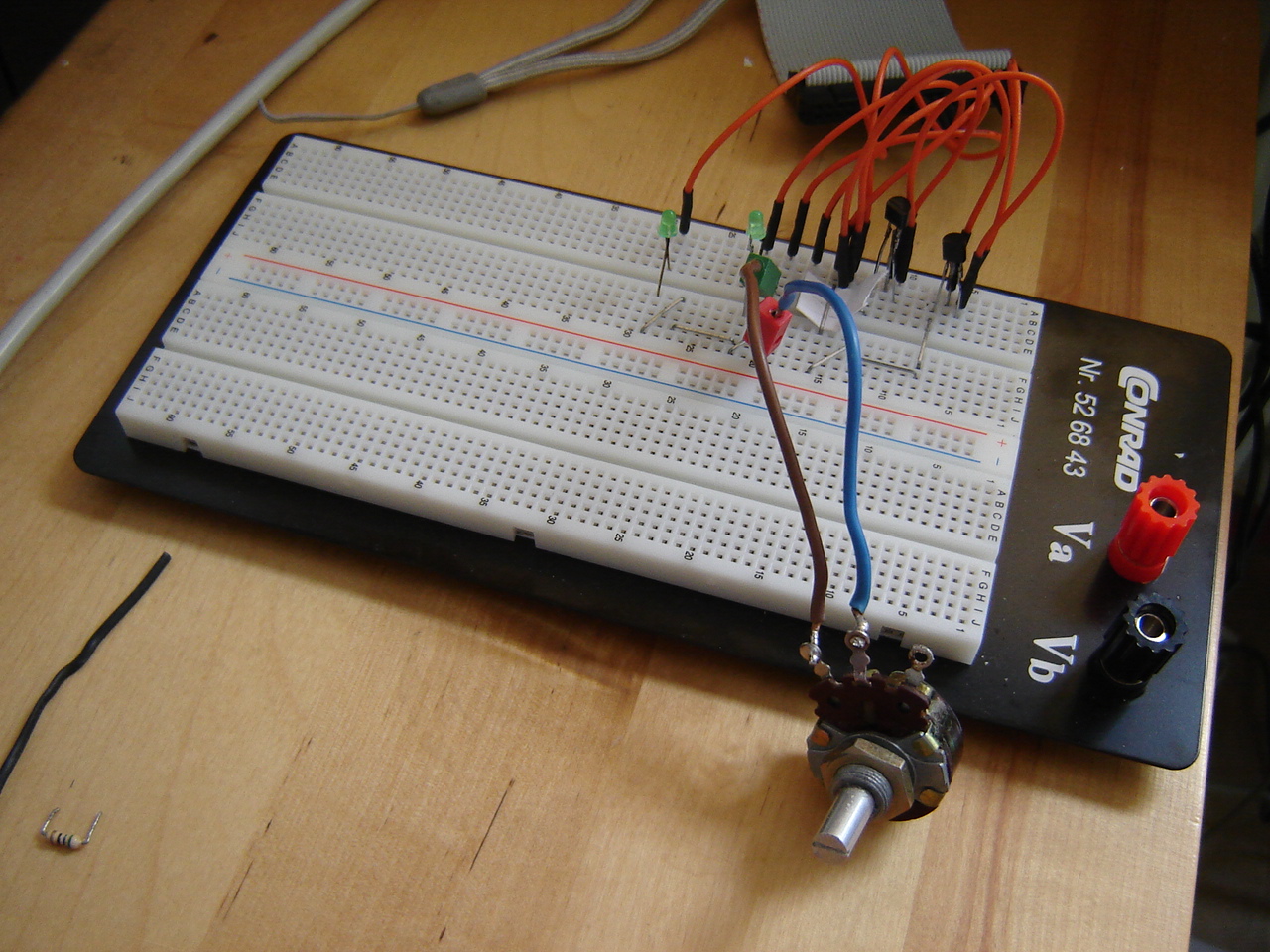
Reason is that the brightness of the LEDs would be dependent on the resistor value. However, with the used potmeter, there is no visible difference in brightness. Unfortunately I don't have another potmeter to continue this experiment right now.
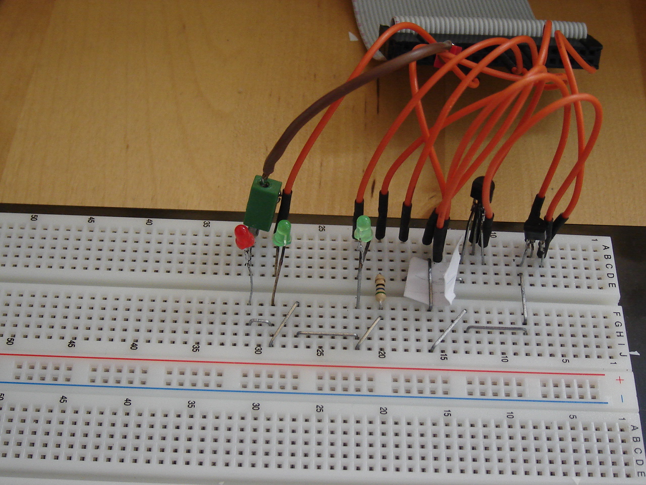
Another experiment is to record the semi-random blinking pattern in a textfile using f= ('<file>','w') where <file> is the filename to write to and w is the writing action. So, when e.g. input 16 and 18 are both low, 'none' will be written, otherwise only the high will be written. After writing, the file needs to be closed which is done using filehandle f, so f.close(). Then, you can also have this writing action indicated by a flashing LED, so I added a red LED that burns for 0.5 second during any write-to-file action as shown in the picture and in this video.
The Python code snippet that writes to the file and burns the red LED on GPIO output pin 31 when GPIO input pin 16 is high and pin 18 is low:
------------------------------
GPIO.output(31, True)
f.write('16\n')
time.sleep(0.5)
GPIO.output(31, False)
-------------------------------------
In the picture and video you can see I use a brown wire to connect the red LED to the GPIO. This is just for substitution as I'm out of orange jumpwires. As shown also in earlier experiments, the red LED burns less bright than the green.
Discovery: The colour detection is still giving problems. After the red, the blue and green detection fail as well. Then I try it after uploading my software to the TXT which means a change from online-mode to download-mode. Now it shows different behaviour: it seems to work although I can't verify it the way I want: with numbers and text displayed. After simplifying the program and uploading it to the TXT controller, some testing reveals it still doesn't work as this video shows.
BB: In a new attempt to create a non-speedy video with the webcam, I change the XVID format into MJPG. What happens is that the video only shows the very first recorded frame and nothing else. The second attempt shows even less: just a very short flashing image. Using VLC, the video can be started and as soon as it starts you have to click pause. If you blink, you might think it only shows black. So after changing back into recording .avi, using the semi-random LED blinking code, I get this 5 seconds video. After this I try the DIV4 format with MPG as well as mpeg extension but both result in entirely back recordings. To be continued...
Arduino: After the last successful play with the e-brace, I found that it fell quiet again. Apart from that, somehow minicom (or Linux ?) managed to swap /dev/ttyUSB0 (to the RPi) and /dev/ttyUSB1 (to the Arduino) which didn't happen before. After removing the Arduino connecting, it took several hardware reconnects to get the RPi connection fixed. To be continued...
23 July:
RPi: After using 1 GPIO pin as input, I start another experiment and break up the Darlington transistor. I put the transistors separately as shown in the circuit image and the picture of the breadboard. The randomness of the result is shown in the screenshot of the code output where 16 and 18 are GPIO pins programmed as input lines, the normal video and the video with RPi camera which is made later than the first video and shows different patterns because of the randomness.
Discovery: The detection of colours seem to go very different than with the RoboInterface: using the USB camera. Using ROBOPro, you first have to select the camera and add colour indication. After that, write a piece of software that uses the detected colours to filter out e.g. red and give it as feedback to the main part of the program. It looks like that a constant integer used in the example program (containing a subtract and a comparator with a constant) doesn't work in my code, as if red isn't red. The next attempt is adding a check for black. Although this seems to work, replacing the object (and thus colour) from black to white to red makes no difference once again. Then simplifying the code, I remove the subtract and the constant, and connect the comparator to the colour-inputs, but again it doesn't work as expected. Doubting the camera works correctly, I connect to the TXT with my tablet, and find it actually does work as can be seen from these saved live camera images.

Using example software from the TXT controller, I find that the red detection for some reason doesn't work. In this video, you can see how my code should work and doesn't detect red either.
17 July:
Discovery: In preparation for the real stuff see this video of the barrier model I built from the construction manual. The software is running in online mode for now, which means that it runs from the computer and is not uploaded to the controller. What I find is that not all building instructions are as clear as could be. For me it's no problem, since I can figure it out. But since it's intended for children, I doubt all children can figure it out (but I know there are very smart ones out there...).
After this experiment, I built another model with a wheel-base from the manual and further leave the manual for what it is. The first tests with the wheelbase show a little defect in 1 of the backside wheels. After replacing a part of the construction, it works fine. With this base model working ok, I can figure out what I can do with it with which sensors.
A first addition to the wheelbase is the TXT-USB camera. I can watch its stream using a special app on my tablet. What I notice is that either the uploaded program works or the video feed. Selecting one stops the other.
Then a program I "write" in ROBOPro, Discovery-test.rpp, should first make the robot drive forward at speed 4 for 3 seconds, then make a 90 degree turn left, a 90 degree turn right and stop. However, the drive forward often goes in a curve, so the 2 motors don't always run equally fast. A small change in the program let it make use of the pulse-count of one of the pulse-motors. In this video, the online-running (via WiFi) program counts 400 pulses from the motor until it lets the motor stop for the first time. After that it turns left and right.
RPi: So far, I haven't used the input function of the GPIO. So I added this to the last circuit (see 10 July entry). The idea is to let pin 16 detect if the LED is burning, and if so, have pin 22 burn another LED. The first setup is to have pin 16 connect to the LED and I find that the LED to pin 22 doesn't burn. So I measure the voltage to pin 16 and suspect that it might be too low for its input. A 2nd attempt is to connect it to the base of transistor 2, and now it does work as this video shows. Conclusion is that the input of GPIO has a minimum threshold voltage. What I also notice is that the red LED burns much dimmer than the green LED, despite its higher voltage. So when I replace red with green, I find it burns a lot brighter, as this video shows. This video with the RPi camera gives another view.
10 July:
Arduino: Back to the Arduino. During some experiments (see 14 June), I put it in programming mode. The result is that in SerialMonitor, it shows ISP now, which stands for In System Programming, and seemingly can't quit no matter what input I give. After another full power-off (USB cable and battery disconnected) another attempt and for some reason it suddenly accepts input again. A final 'q' results in 'OUT ISP' and the message 'Choose Action'. So although I'm back where I started, the gain is experience..
Discovery: I've decided to let the C++ go for now and see what's possible with ROBOPro, the graphical programming 'language' for fischertechnik. It seems it has a lot improved with additions such as floating point which is common in C/C++ and Python. So in the coming time I will build the examples models and see where it leads.
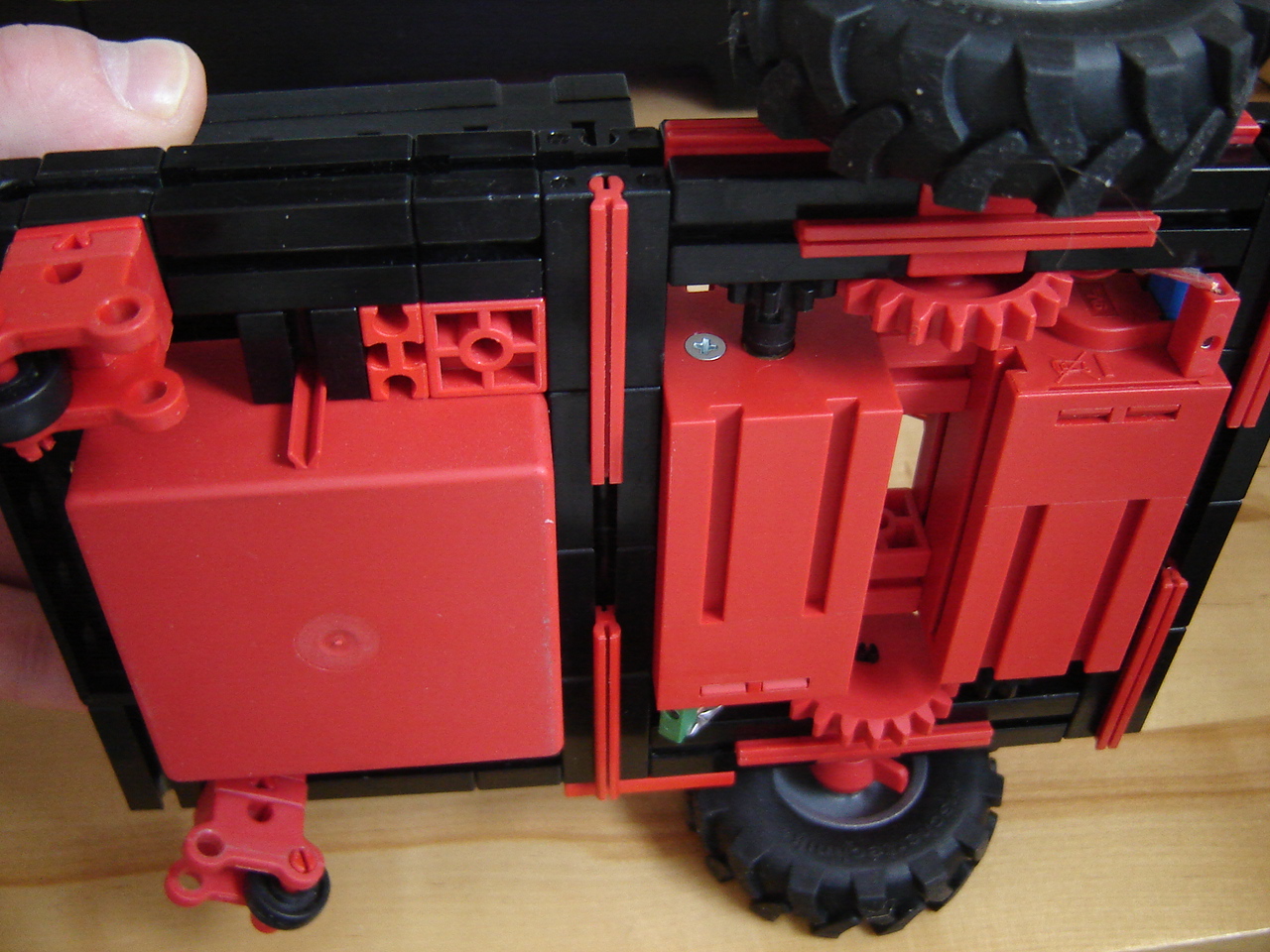
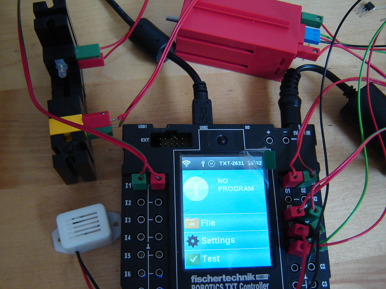
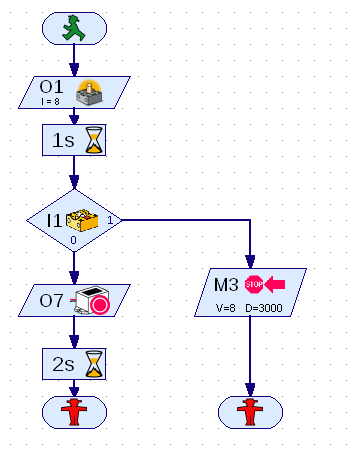
For a quick test, I build a small circuit: controller, lamp (O1), light-sensitive transistor (I1), an encoder motor (M3) and a buzzer (O7). The flowchart graph actually is the program as it runs in ROBOPro. As usually, there's a catch: the transistor doesn't work properly. For some reason it always takes the 1, no matter if the light is blocked oir not. Measuring the voltage directly at the transistor always shows 0.1 V which indicates it doesn't detect light. Replacing it with a transistor which has proven to work doesn't change the situation. Conclusion should be that the wiring is the cause, but since the proven transistor doesn't work either I doubt replacing the wiring is the solution.
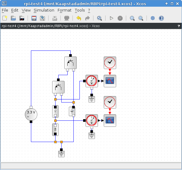
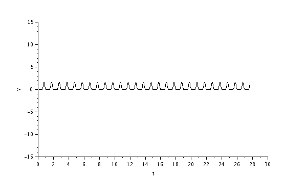
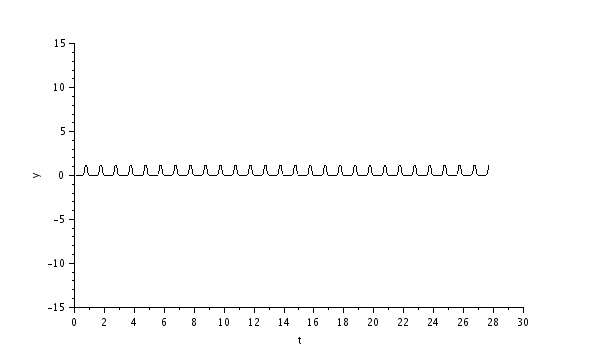
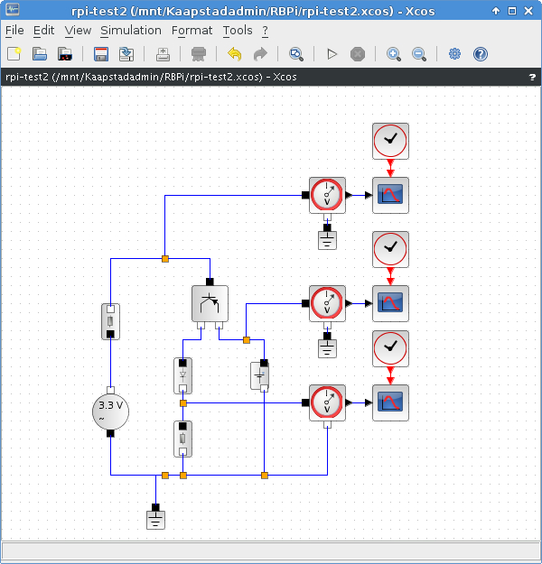
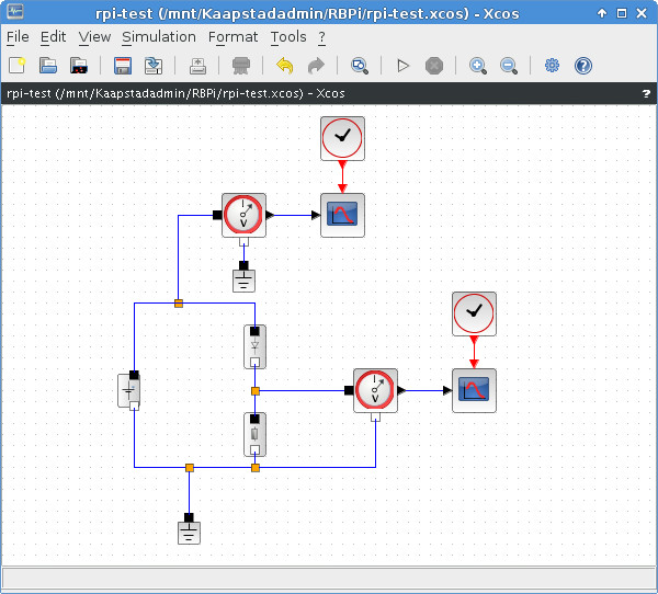
RPi: My next experiment is using 2 NPN transistors and 2 LEDs in series. In Scilab/Xcos simulation this gives that the 1st LED burns fine, and the 2nd LED burns very weak. Testing with the real circuit, the multimeter shows 0.40V on the emitter of the 2nd transistor: too low to let the 2nd LED burn. However, taking out the 1st LED and connecting the collectors to each other, creates a Darlington transistor as shown in the graphs and this video. The 1st is the voltage directly after the 2nd transistor.
3 July:
RPi: I've made another .avi video of the LED blinking via the transistor using the webcam. So although it runs the same length as the other 2 videos (made with the Sony cam and RPi cam) it looks like it once again is sped up. I'm using fourcc = cv2.cv.CV_FOURCC(*'XVID') to create an .avi video and despite examples with other formats like mjpg, I haven't found anything else but avi that delivers a good video using the webcam.
Using the existing circuit, I wondered how fast the GPIO can be switched on/off. So I changed the sleeping time in my code gradually in seconds from 1 to 0.01. It turns out that 0.015 is the shortest sleeping time that shows actual blinking of the LED with my naked eye. In this video the blinking is barely visible (it goes on/off for 500 times).
After desoldering more parts, I got a hold of a S9014 transistor, which is an NPN type. So now, the circuit looks likes this in Scilab with the simulation signals as shown in the blog of 25 June. This video doesn't show any difference in LED blinking but the wiring is definitely different.
Discovery: Apart from the earlier mentioned sources, fischertechnik also published the rootbuild software of the controller. Using this you can work in offline mode: scp your own binary and have fun. Just the rootbuild needs to be built on your local system and uses git as well. Before building, it needs to be configured like any other kernel. In this case, it can be configured as an Eclipse plugin. And here's a catch, for me. Eclipse is a really nice IDE but a real memory hog. As such it's not recommended to use on low-memory systems with only 500 MB. So next try is to build it on a different system and then copy it to the TXT. Following a tutorial, I find that I have to use a newer Eclipse version (Luna) than I have (but not the newest), which proves hard to download. The fact that it's not the newest (at time of writing this blog: Mars) is because the buildroot-plugin supports up to Luna. After that, I need to give the plugin site, which I have to give different than the tutorial tell. Then, after copying the modified sources to a newly created C++ project it seems to build with warnings. To be continued.
25 June:
Mirft: After the stabilization of all 3 hip/legs, it turns out that the last 2 cause a slightly wider hip. So I decided to replace the 1st stabilizing construction with the same one as the last 2. With this stabilizing act, and the lower legs attached again, a simple lifting experiment shows a weakness of the legs. When there's an uplifting force, the leg bents uncomfortably right below the 'knee'. This is (for now) solved with a supporting piece.
Another problem still present is the detection of the horizontal extreme position of the legs. To detect this, a mechanical mini on/off switch is a possible option, as shown below. However, as wiring and location show, it both placing in the middle and at the sides give problems.
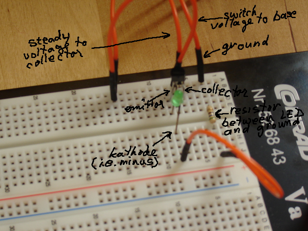
RPi: An expansion of the LED experiment is to use a transistor, which is actually an electronic switch. In the shown schematics, the alternating voltage connects to the base of the transistor and causes the output voltage on the collector between the LED and the resistor to go on and off. In practice, it doesn't work like this. The sine voltage of 3.3V actually is a GPIO pin that will be programmed to go on/off. As a result, the output voltage looks more like a block wave (on/off) than a half-sine (slowly on/off) as shown in this video. From the RPi side, I created this HD video. There is also an oddity. The first simulation was with an NPN transistor and worked great, showing the output as intended (in the graphs below). When I found out that the used real transistor is a PNP type, the simulation was redesigned (as shown) and fails to work
19 June:
Videos: I have put older videos from the fischertechnik Schoonhoven and Veghel conventions on Youtube, which were previously only on Picasa.
Mirft: For the walking robot Mirft, 2 legs/hips still needed to be stabilized. Since the part I used for the rear hip stabilization is out, the solution is shown in the picture below with a current overview next. I also created a narrated overview video which is only available via this blog and the video page. So with the stabilization hopefully done, some serious software testing can be done.
RPi: The next experiment is connecting a fischertechnik (ft) buzzer parallel to the red LED and a 9V ft motor parallel to the green LED. The buzzer works nicely, but the motor doesn't work and causes the green LED to stay out. After disconnecting the motor, the green LED burns again. Also, when simply replacing the LED with the motor, the motor does nothing. Although a test shows that the motor is able to run on 2.5 V, the motor apparently is too heavy for this low-power circuit which runs at 3.3V. There exists an RPi motor controller board, that uses part of the GPIO and allows a motor and an extra batterypack to be attached. The heart of this board is the SN754410NE chip, which is an H-Bridge that can control the speed of a least 1 motor.
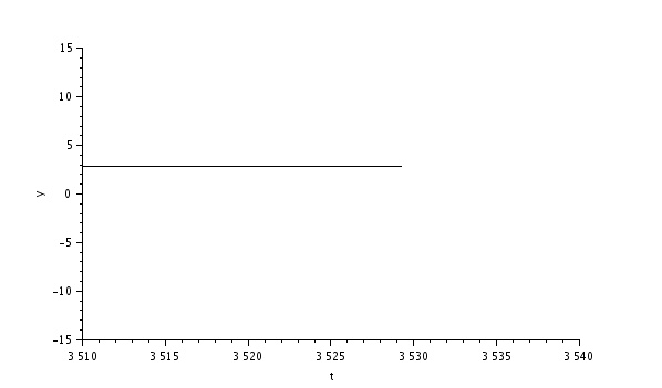
To make sure a circuit can work without using hardware, you can of course use a simulator, such as Scilab-Xcos. The circuit with the green LED looks like the screenshot below and the next screenshot shows the voltage between the resistor and diode during simulation.
Discovery: fischertechnik (finally) released documents to enable programming for online mode without using ROBOPro with a simple trick (replacing a default IP address with either 127.0.0.1 or localhost) for download mode as well. Of course, when you intend to use download mode, you also have to cross-compile the executable for ARM before uploading to the controller. The example software is written with Windows in mind and uses winsock2.h. This needs to be disabled: either with #ifdef WIN32 or commented out entirely. Also SOCKET isn't used and according to various posts this should be replaced by int (i.e. integer). After compilation there are undefined references which would indicate library issues. After trying with the use of -I (to use headerfiles) and -l (to use libraries) switches of g++, the errors remain.
14 June:
Arduino: Last time I told about the e-brace without giving real hardware info. So here goes: it uses an Atmega328 for each of the light, movement and sound. For the controller the Atmega324 is used.
Using information from the Elektor e-brace forum, I can successfully use the Serial Monitor and switch on/off the various modules: 1: light; when active the LED shines red, 2: movement; when active the LED shines green, 3: sound; when active the LED shines blue. Since there isn't yet a program loaded, option 4 doesn't do anything yet. So, using data from the gadget.h Linux library (to be used in software) via Serial Monitor you can read/set the e-brace without real programming. With this info I give e.g. '8' as input and it shows different X-Y-Z coordinates after moving the e-brace to a different position.
In this video I show the switching on/off of the mentioned modules using the Arduino Serial Monitor. Then I wanted to make a video that showed this Serial Monitor on screen and my hand moving the e-brace. However, in video-mode the camera has auto-focus and when I point it at the laptop screen the focus changes constantly. So when I hold the e-brace in front of the camera, it focuses on the e-brace and the Serial Monitor goes blurry. So much for a video experiment. Oops.
BB: Recently I succeeded in taking pictures by using video with my Logitech webcam. Since it is quite cumbersome to copy each picture to the laptop in order to view it, I decided to install gpicview which is also used on RPi. This has a rather small memory footprint (i.e. uses only little working memory when in use) so it is started quickly.
For creating a video of the LEDs without taking images and using the webcam, I find a piece of code on the web at Python OpenCV tutorials. With a slight change I can create an avi video which, to my surprise, lasts only 6 seconds while the full 20 seconds program is run. As if the video goes fast forward and shows it 3 times faster. Other formats than avi haven't yet resulted in usable videos.
RPi: In continuation of the experiment with 2 LEDs, I tried to make another HD video with the RPi camera. It takes several attempts to get an acceptable result, for various reasons. In no particular order: the green LED is out of sight, the red LED is not visibly burning on camera (it is visible with the naked eye) and the RPi camera is out of focus.
The "out of sight" is easily solved: just move it in sight. The "not visibly burning" is because it doesn't burns as bright, caused by a higher resistor value. I can't change that for now, since I can't find a resistor with a lower value than that. I finally "solve" this issue by changing its position upwards, so the red LED faces the camera. The "out of focus" can't be solved since from documents it appears that the focus is set to distances of at least 1m. So 10 - 15 cm is an oops. The HD video will be published anyway. After replacing the improvised setup with a breadboard, it looks much better. And after replacing the fischertechnik wires from the GPIO with a flatcable it becomes electrically safer on the GPIO side and gives more flexibility in the whole setup too.
On the resistor values: the one for the green LED is 56 Ohm, the other is 560 Ohm. Fortunately, I find another resistor 56 Ohm resistor, so now both LEDs burn equally bright.
9 june:
Mirft: A possible solution to the instability of the hip/leg construction is shown in the latest pictures on the Mirft page. Unfortunately, so far I lack 2 items of the same part to stabilize all 3 hip/leg combinations. After putting the new solution in its place, it works better although the hip hinge is not really solid, but it will do for the current set of experiments without putting much weight on it.
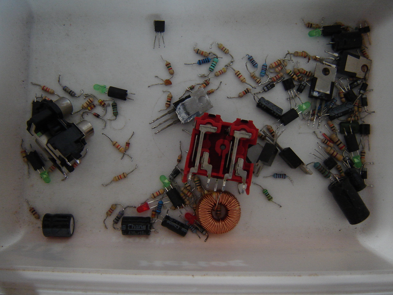
RPi: I found a nice little project to create a blinking light using a resistor, LED and the GPIO of which I could make a video with the RPi camera. So now I'm desoldering LEDs, resistors and such from old PCBs to get a stock. Too bad I don't have a breadboard i.e. a board for the use of electronic components in experiments.
Improvising with a 50 Ohm resistor, a green LED and fischertechnik wiring, I make a circuit. With the circuit starting at GPIO pin 1 (3.3V), the LED burns bright.
The next experiment, is to connect the circuit to GPIO pin 7, which is a controllable pin. However, after setting the burning time to 3 seconds nothing happens. It turns out that this is because the GPIO is only accessible as root. So, sudo python GPIO-led.py works fine and filming it gives a nice 5 seconds video. Since this is rather short, I extend the program and another video is made with the LED multiple times blinking. After this, since the RPi has a camera of its own, a 20 seconds high resolution video is made with the blinking LED. Both videos are public on Youtube and on the video page. The third experiment is connecting a red LED to pin 30 (GND) and pin 33. With a slight adaptation to the program, there are 2 LEDs blinking. The only downside with the improvising is that the wires quickly get messy.
Video: I got the good suggestion to combine the short videos into a larger one and put that on Youtube. Although a first result using Openshot is nice, the question is in which format and resolution it has to be saved: there are a LOT of choices. Another option is the use the online Youtube video editor and the first one from 2008 using this editor is online via the video page. All takes time though, so I will decide how to go on after getting feedback. Without feedback, it stays with this 1 video.
Arduino: on the Electronics & Automation trade show at 4 June, I walked 7 "steps" to collect an e-brace: get the PCB, have the firmware flashed, get the USB cable, get the battery, provide it with an ID, get a wristband and do a handshake. The actual final step is to install an app on your smartphone or tablet to see the IDs of those you did an handshake with. And this was the downside for me, because the app required the phone/tablet to have Bluetooth 4, and my tablet has 3.
This device is an Arduino, so actually another embedded system. To work with this, I installed the Arduino IDE and when starting up got an headless error. It turns out that it uses openjdk rather than Oracle/Sun java and I had only installed the headless version of it. There is this command update-alternatives --config java that shows which java is standard on the computer, and it only showed openjdk, while for Eclipse I use Sun java. So I decided to install the non-headless version of openjdk after which the Arduino IDE starts nicely. The device connects with the FT230X USB cable, which is /dev/ttyUSB1. Following the documents, it turns out that although it can be selected, it can't be opened: permission denied. This is because I'm using the IDE as a normal user. After changing the start into su root -c "/opt/arduino-1.6.4/arduino", the serial monitor can be accessed.
A difference with the RPi and BB that I found so far, is that you can't login to the device. You can only upload or download software, so it's a new experience. I will see how much I can do with it this Arduino.
5 june:
Discovery: At the fischertechnik forum, a member gives an example of making a screenhot. This starts with copying the contents of /dev/fb0 to a screenshot.raw file and finisches using avconv for converting raw to png. It gives a nice screenshot (or better: screencapture) of the touchscreen. The first results I got with the copy of the contents /dev/fb0 were distorted and I thought it was from the USB camera, but in hindsight it looked indeed like the touchscreen.
Mirft: The fixation of the string to the hip-wheel is again tried, this time with a small part where the string is stuck more firmly. A picture is shown on the Mirft page. A hand-driven test forced 1 of the fixations out of its location because of the tension on the string.
Another problem is that the legs come away from the hip way too easily: a bit of tension from the string is enough. So the mounting of the legs probably have to be redesigned.
Youtube: The Youtube videos on the videopage can't be shown embedded since this is a simple website without javascript. So you have to use either Google+ or go with the "blind" numbers. For the videos from TeamBuildingDay 2008, each contestant's first attempt is made public and they're all uploaded now.
29 May:
Videos: The large series of videos from the Robotmc TeamBuildingDay is being uploaded to Youtube (and video #1 is public). Because of the large number of videos, this series will be on Youtube step by step.
Picasa: I tried to watch videos via Picasa again after updating flash, but it still doesn't work. Via Google+ it does work, but by far not everyone uses that.
RPi: Until now, I first used the raspistill command to take a picture, and then using my code to read and process it. Next step is using the command from inside Python so all of it can be done using Python. After trying and some help from the net, the correct command is subprocess.call("raspistill","-o","image.jpg"). The difference it size after resizing to 20%: 2958186 against 73603 bytes. The pictures can be found at the RPi page.
BB: The resizing results in a clear difference. The original size is 358672, while the 20% resize is 20222 bytes: 460x480 vs. 128x96 resolution. The pictures can be found on the BB page. Obviously, the RPi cam works standard in much higher resolution than the Logitech webcam. An interesting fact is that cv2.imread on the BB only seems to work with png, not with jpg. I tested with jpg images, and they didn't load correctly. The example-code I used to write my code works with png as well.
Discovery: I'm still waiting for the documents to be made available by fischertechnik, so I can continue.
Mirft: In order to keep a leg moving correctly up-down and forward-backward, the lenselights and the foto-transistors have to work properly. Since I've connected those to the slave-controller, the upper foto-transistor for the first leg is t.Digital(9). For now it seems to be working. I hope I can make/publish a video soon.
25 May:
Website: Because the material on both RPi and BB grows, I decided to give them both their own page.
RPi: Using the earlier taken high-res image, it turns out to be rather easy in Python with OpenCV to display the image in a much smaller size: cv2.resize(image, (0,0), fx=0.2, fy=0.2) which reduces the size of the image to 20% of its original size. Next comes saving it using cv2.imwrite(name, image).
BB: Taking code from a Python example on codeplasma.com, I can now use my webcam to take an image and display it on screen. A note on using a webcam on the BB: there are cameras such as the LI-5M03 that can use the Digital Signal Processor (part of the BB's OMAP CPU). However, using this DSP requires the BB to run an old 2.6 kernel and the DSP driver is obsolete, as I found out during my MSc thesis. So my USB webcam works pretty fine with this code. This also leads to a new schema for the BB setup, as shown on the BB page.
Videos: I've uploaded more convention videos to Youtube and made the first of each year publicly accessible. So now you can subscribe to my channel, if you like. The other videos I still keep private, so only accessible from the blog or the video page.
22 May:
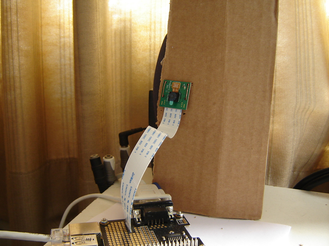
RPi: I'm using only VNC to have a desktop and after a short online search it turns out that the raspistill and raspivid commands give no preview because this is a superimposed videolayer on top of the desktop and as such not available on VNC. The Pi camera mounted on a piece of carton using parts of a paperclip.
Using raspivid I create a 5 seconds video, again in h264 format. The video is recorded in 1920x1080 resolution. So far, the only way I find to replay the video is using VLC. I installed this on the RPi, but since the replay-area on screen is larger than the VNC screen, this is unusable. Solution is to copy it to the laptop and replay it. An attempt to upload it to Picasa ends with the message about unrecognized video format: h264 cannot be converted. Youtube gives a warning but successfully takes the video.
Using OpenCV2 on RPi turns out to be recommended for Python. C/C++ is advised not to use, because RPi is focused on Python. However, processing and showing a testpicture using OpenCV2 does not show anything at first but an empty window and ending up with the message that the window "may not be responding". After removing some code and only reading and showing an image it works, although the image goes offscreen due to its resolution. I wonder if this happens on BB as well. A test on the laptop shows the earlier taken picture in huge resolution which goes wide off screen as well.
Mirft: To see if adding a motor on the opposite end of the rod can be a solution to the problem I described yesterday, see the pictures and video. A first test seems to be successful.
BB: Using OpenCV turns out to be a problem. After the installation of OpenCV, the OpenCV2 instruction imread() is not available, so the suspicion is that OpenCV1 is installed instead of 2. To install v.2 I'll have to download the source and cross-compile. Edit: I made a mistake, so my suspicion was wrong. OpenCV works great on BB as well.
Mydfir: I realized that these videos were not on the video page yet. So I added them and put them on Youtube (unlisted) as well.
Videos: the ft 2009 convention videos are published publicly on Youtube.
20 May
Discovery: Via the ft community forum I received an answer on how to make snapshots with the ft USB camera using an imagestream on the TXT. This works nicely and I put it into a script. These jpg snapshots show the driving robot and TXT controller at a resolution of 320x240. The reason of the double image is uncIear; I suspect the stream is slow and needs some time to grab.
Working with ROBOPro via wine on the TXT works fine except for the camera; this gives a black image in preview. I'm not the only one, according to the forum. Since it works via wine, I'm more than happy to remove VirtualBox/Win7 from my laptop. 45 updates in a few days ("do not shutdown"/"configuring updates") is too much for a proprietary operating system.
RPi: I now also have the Pi-camera, so I can start experimenting with OpenCV on Python and possibly C or C++ again.
A first test using raspistill resulted in a nice picture. However, although the video raspivid delivered an .h264 video, I can't replay it yet because players don't recognize it. Also streaming video using nc and mplayer has no results yet.
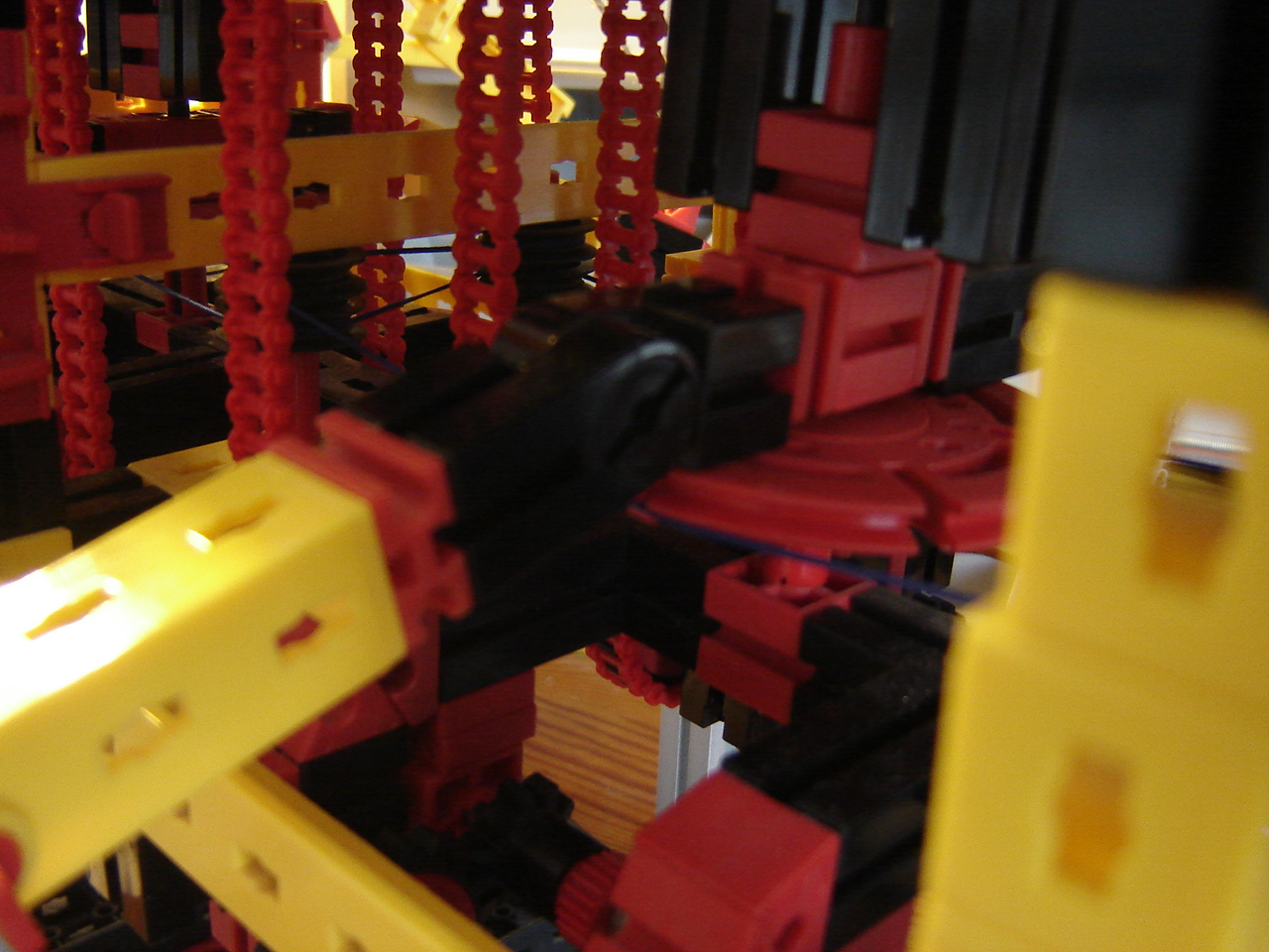
Mirft: apart from the software, the mechanics are naturally very important. The idea was to have the upper leg move in an ellipse. However, an easier way to go seems to lift the leg completely, then go maximal horizontal and go down again. While testing this idea a mechanical problem with the chains surfaces, as shown in this short video (Picasa) or this video (Youtube). A first solution is to loosen up the tension in the 2nd and 3rd chain (oppositie the motors), but this gives no real solution. Then it seems that the rod at the end of the first chain (so at the motors side) is not sufficiently inside the gear, but putting it fully in gives no solution either.
18 May
Discovery: Because the steppermotor doesn't run, I look at a few sample programs and find that those are quite similar to mine. So I try again, and this time it works: the steppermotor runs. No clue about the difference. What I notice, is that the batterypack is emptied within 10 minutes. The TXT controller is power hungry and with a motor attached it goes fast.
What I forgot is that on Linux, a .bin file usually has to be changed into an executable by chmod +w <file>. However, after doing so with Test3.bin, this error popped up: line 1: syntax error: unterminated quoted string. Doing the same with Test.bin results in even more errors.
As an aside: I also managed to install ROBOPro via wine, which seems to work. Next comes testing it with the TXT.
RPi: When programming in Python, obviously there are 2 versions. Via the desktop they're indicated by IDLE (2.7.3) and IDLE3 (3.2.3). For minicom (and thus in any terminal session) I have to start python3 to get this version.
A small programming example shows a remarkable difference between the 2 versions. name = input('what is your name') gives an error in 2.7.3 while it runs fine in 3.2.3.
Programming the serial port:
RPi: After installing py-serial on the RPi side and pyserial on the laptop side, a short program is written to see what the results of serial communication are using Python instead of C. Some quick tests: using sudo python serialtest.py on RPi towards the laptop it shows no delay nor missing characters on the laptop. Then a similar test from the laptop towards the RPi shows there's no delay nor missing characters on the RPi either.
BB: After installing python-serial, I can test the same Python code on BB. There is immediate response on screen and there are no characters missing. Hence I have to assume for now that my C code is not working as it should. The Python code was written in version 2.7.6.
15 May
Discovery: Since I still can't figure out which /dev/ corresponds to which in/output, I've decided to create a program using RoboPro, and then see what happens. Unfortunately, nothing happens. In test mode all in- and output works, but nothing happens when a test program with steppermotor (runs the motor for 5 seconds) is run.
The test program using a simple motor does work. The sourcecode is named Test.rpp and its content shows as an XML file. After compilation/uploading to the TXT, it turns out via ssh that the binary is named Test.bin and is located in the ROBOProFiles directory. On the file-list via the TXT menu only the names Test shows. An attempt to run Test.bin from the ssh-terminal commandline shows it won't work that way: with 644 permission it's not executable. Running it from the TXT display works fine. So more stuff to figure out.
12 May
Movies: Because of site-statistics I realized that my announcement of movies make visitors to go straight to the movies page, while the BB and Discovery movies were not made available there. This error is now corrected.
RPi: A short video is available via both the movie and the embedded systems page.
Using Python-Idle shows an unexpected difference. When I start the Python shell via minicom, v. 2.7.3 is started, but when I start Idle, it uses v. 3.2.3. And since I can't logout from the pi-user, seemingly due to a frame buffer issue, I will have to deal with this for now.
Picasa-videos: right now, they're only watchable on Picasa+/Google+. From the Picasa forum I read that things at Google are changing and maybe are fixed by the end of May. Until then please watch my new videos on Youtube. IF this whole video stuff gets fixed, I will remove the videos from Youtube. If NOT, I will see then.
11 May
Mirft: I received the 1:125 motor and after a short test I'm happy. This is indeed the motor I need for horizontal movement of the legs. After replacing the 1:50 motor, as expected other problems surface. So there's a task list.
- improving the connection of the string to the hip.
- the motor keeps pulling when the utmost position is reached so either the running time of the motor must have a limit or sensors have to be added.
- reprogramming is badly needed. Using Python for this again.
To show the new motor and make things clear, I've posted some pictures.
Discovery: Because of the Picasa issues ("invalid parameters") that make my videos unwatchable, I've put the video on Youtube. Check for the video link on the Discovery page.
7 May
Discovery: I spent some time trying to find out which /dev/xxx files could belong to the interfaces I1-I8, M1-M4 and C1-C4. After all, when I want to read out a sensor, count pulses from a motor or control the speed of a motor I need to address the correct device file. I have asked fishertechnik for more information on this, so hopefully I can start the actual programming.
In the meantime, I created a short video to show more, which you can access from the Discovery page.
4 May
Discovery: After the first exploration of the TXT controller, I found it cumbersome to have to switch the WiFi connection from the TXT to my own WiFi. It already went wrong twice with nfs mount errors as a result. Then I realized the solution was easy: use the wired socket for the internet connection and nfs mount and use the WiFi for the TXT connection. Fortunately I had a spare network cable and a network switch close at hand, so the connection problems are solved.
Another thing is that the TXT is not just a controller. Having an ARMv7 CPU makes it an embedded system as well. Onboard compilation like I do with the BB and RBPi is a no-go because the TXT safety document clearly states that a C/C++ compiler is not delivered with it. This is simply solved by installing the Linaro cross-compiler on the laptop with is standard available in the Ubuntu repositories. So now I will do cross-compilation on the laptop and copy the binary to the TXT using scp (secure copy). A simple test program HelloWorld as expected confirms this idea works.
Another topic is how to get an image from the camera without using Windows. I tested it shortly using Windows and the hardware is ok. In the documentation is stated that the camera uses /dev/fb0 as framebuffer to store an image. Then it is simple to copy that image into another file: e.g. cp /dev/fb0 video. However, the format is probably RAW and there are multiple RAW formats. So the next task is to figure out how to get a usable image.
1 May
RaspberryPi: During this week I conducted the serial communication test on the RBPi several times and oddly enough, the behaviour of minicom on RBPi changed: this time into rather inconsistent behaviour. It either did not show anything, or it showed partly, or completely. It also occurs that minicom reports "Cannot open /dev/ttyAMA0!" after receiving and displaying a string.
On Mirft: After looking at the webshop http://www.fischerfriendswoman.de/ I found a powermotor with ratio 125:1 which would result in a much lower speed of the horizontal legs movement. So I ordered it...
Then the pneumatic hand. After an hiatus of some months, I tried to upload the Basic-language version of the original Python code again in order to have the hand work in offline-node. Unfortunately, nothing has changed and I still get (among others) this error: Error uploading Program: Return value for 0xC0, 0x20 is 0xef. Since the Basic expert has no clue and the (seemingly) only other Linux user on the forum has no clue either, I've asked the manufacturer but no answer as yet.
And on 30 May I received the TXT Discovery set. After unpacking, there are 2 white plastic (why plastic ?!) crates with parts, a manual and a cd with ROBOPro 4.1.5. Using Linux, I won't use it for programming but it is needed for some tests and firmware updates and before doing anything with the controller, the firmware needs to be updated from 4.1.0.0 to 4.1.6.
Since I don't plan to use Windows often, I will install it virtualized. I tried to install it under wine but instead of a setup.exe, it comes with a setup.msi and wine msiexec /i <installer> fails to run. So I had to install Windows7 in VirtualBox. After installation of Windows7, ROBOPro 4.1.5 is installed from cd/dvd, and this leads to a complete nightmare because it installs by default in Users\..\.AppData\. And any directoryname or filename starting with a dot is hidden and in Windows not indexed. So while the software starts, any file it searches won't be found such as any pdf file ROBOPro looks for. Of course there's a work-around like using TotalCommander and then search for pdf file and then automatically open it in a pdf reader but for the average computeruser this won't work.
My first solution to is to remove ROBOPro and install it into the normally accessible directory C:\ROBOPro using advanced installation. But even then it won't find pdf files or firmware to update. It turns out it is looking for the files in the old .AppData location. Ugh. As I don't find a way to change the directory it looks for, I reinstall it in the users directory again and this time the firmware is upgraded successfully to 4.1.6. Yay.
After this rather slow start, of course some experiments. It turns out that the TXT is a WLAN dhcp server. This means I can't access it from my own LAN but instead have to disconnect the laptop from the LAN and connect to the TXT. There is a document with security advices and explanation on how to change settings such as passwords. However, there is no information on how to proceed and program from a Linux based environment although the TXT itself is Linux based: I can make a good ssh connection to the TXT.
Besides that, at the fischertechnik 2014 convention, I had a talk with the Knobloch boss who assured me that there would be drivers for Ubuntu. Since I know there are more people waiting for these Linux drivers, I hope I don't have to wait very long.
24 April
Further tests on the laptop to RBPi communication show that minicom on the RBPi doesn't have to be restarted after each test. Each received string is written over the last one. However, the received characters are not the fully sent string. Examples: 23456789098765432 is displayed as 98765432 and abcdefghijklmnonmlkjihgfedcba is displayed as jklmnomlkjihgf. So not just the beginning is missing, the end is missing as well.
Although on both the BB and the RBPi apparently characters are lost when receiving, they are not the same chipsets: BB has omap-serial (hence /dev/ttyO2 with capital letter O) while RBPi has AMA which according to this post seems to be AMBA.
For now, the question remains: why do they loose characters ?
23 April
Today I received the Serial Pi Plus and mounted it. Starting a connection with minicom was easy using the null-modem cable. See the pictures. Just too bad I don't have another null-modem cable, because now I can only have 1 serial connection at a time: either the BB or the RBPi. A kind of XOR situation. My serial communication code has of course to be changed. The serial port on the Serial Pi Plus is called /dev/ttyAMA0. After that, writing to minicom goes well. Interestingly, writing from both BB and RBPi to minicom on the laptop keeps working without a restart of minicom while in the other direction it requires a restart of minicom after each write.
22 April
So far I've been reporting about the BB, but I thought it was time to spend some time with the Raspberry Pi B+. I ordered the Serial Pi Plus, which is an add-on with an RS232 connector. Using this, I can do exactly the same as with the BB: using a minicom session for debugging. Another option would have been to use a PL2303-based cable, which uses 4 GPIO (General Purpose Input Output) pins for serial connection and plugs into a USB port of a computer. However, the website says it's EndOfLife, Besides that, it also delivers power to the RPi, which it already gets.
Also, the RPi should do fine with imaging. This leads to some experimenting with 2 programs: guvcview and xsane. The first is a nice tool with which you can in detail adjust the cam settings and record both images and video's. However: apart from clearly recording sound, all images and video's are black, no matter which settings. To see if my webcam (Logitech QuickCam Fusion) actually works I use xsane (which I frequently use to scan images with an ordinary flatbed scanner) and with great result. So the question is why guvcview shows only black. During my MSc thesis, the combination of this same webcam and the BB-xM worked fine on guvcview.
19 April
I created a short video explaning how the BB is connected. More video's probably to come.
17 April
On the serial communication from and to the BB, I've found an interesting fact. After searching the net, I noticed a remark that you actually can read from /dev/ttyO2 but that the first characters are ignored. To test this, I changed my usual test-string length from 6 to 20. When then happens, shows that the port is read but that the number of read characters varies. With the character string "1234567890987654321" sent several times, the received (or more accurate: displayed) strings are: 7654321, 890987654321, 4567890987654321, 7890987654321, 34567890987654321, 7890987654321.
- After the sending of a character string, I have to restart both my own program on the laptop and minicom on the BB.
- Now that I know this receiving behaviour, I have to change my code a bit on the BB side in such a way that it can receive a longer string.
Of course, the question is: why does it show this receiving behaviour in the first place.
9 April
This past week I've been busy with the BB communication as well as the Mirft simulation.
On the BB, I decided to do a different test by installing Minicom and see I characters sent from the laptop would appear in Minicom on the BB. The result was that it doesn't. Even worse: despite the correct settings, Minicom shows after a lengthy delay the message that it "cannot open /dev/ttyO2". So the question is why can it write, but not read ? Some suggestions are it may have to do with uboot settings or even kernel issues. I'm not convinced about either.
The Mirft simulation has not made progress in that it shows the intended movement. Somehow, there's a discrepancy between my model and the inverse kinematics possibilities: location can't be reached. Which I seriously doubt. In the mean time I've drawn a sketch using Inkscape to illustrate how the legs should be able to move. So if you combine vertical and horizontal, you also can have an elliptic move. The text is inserted by using textext.
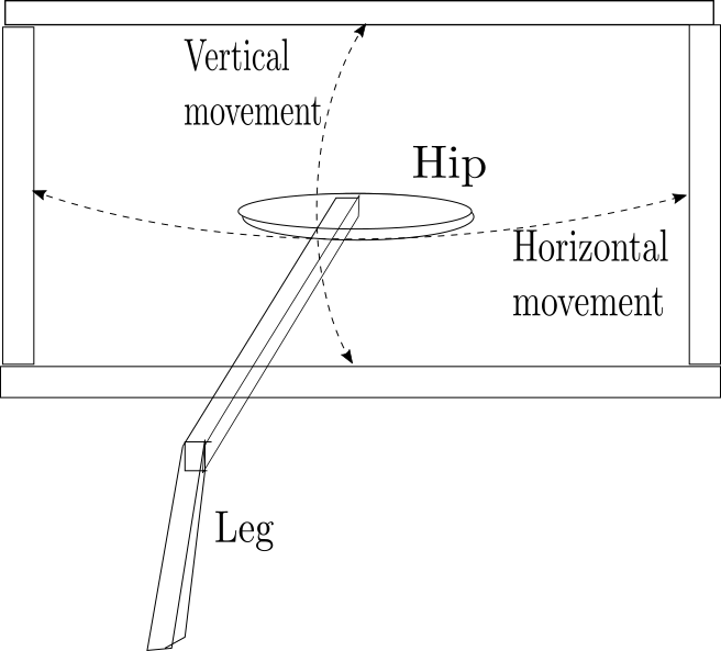
To be continued.
2 April
After some attempts to become familiar with git, I finally managed to add my robotics Python code in 3 separate repo's. The code won't be of much use for anyone, since it's for the combination of Linux-ft RoboInterface-ft DataLink but it gives an nice inside look (I think). My GitHub handle is hvn52.
27 march
The serial communication is still not working the way I want. Using minicom, I can see that the text from the BB is received. However, when I use my own code, there's no prove that anything is read from /dev/ttyUSB0. I've added some code that writes to a text file whether anything is being read or not, and the text being written is telling me nothing is being read. Maybe my reading code is wrong...
Also some more action on the simulation. The new robotics toolbox is installed and while the demo shows how it's done...my own manipulator (i.e. robot) is not moving. The code shows 2 errors: a point is unreachable and some submatrix error. Somehow I hope this is a kinematics bug, and not my fault. Will see.
18 march
After some online consult on strings and character arrays and re-reading K&R ("The C-programming language" by Kernighan and Richie) about it, I managed to send keyboard input over the serial port and read it in minicom terminal. Odd is though, that now suddenly I have to run the program using sudo. Although this is quite logical (after all, writing to/reading from the serial port uses system calls), earlier it just worked without sudo.
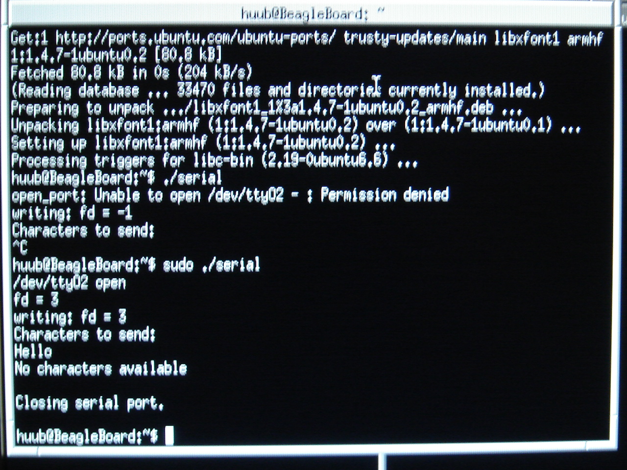
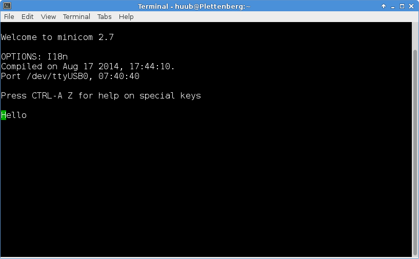
17 march
I resumed serial programming on the BeagleBoard and found that I made 2 typos: /dev/tty02 instead of /dev/ttyO2 and an if-statement comparing to 1 instead of -1. Oops. The result is that I can now send characters ("Hello") over the serial line and actually see them in on the commandline in the terminal on the laptop. Yay.
A few more (incubation/check) days to wait until the improved robotics toolbox is ready to install in Scilab. Can hardly wait to get on with that.
Last for now is an updated graphic of Mirft.
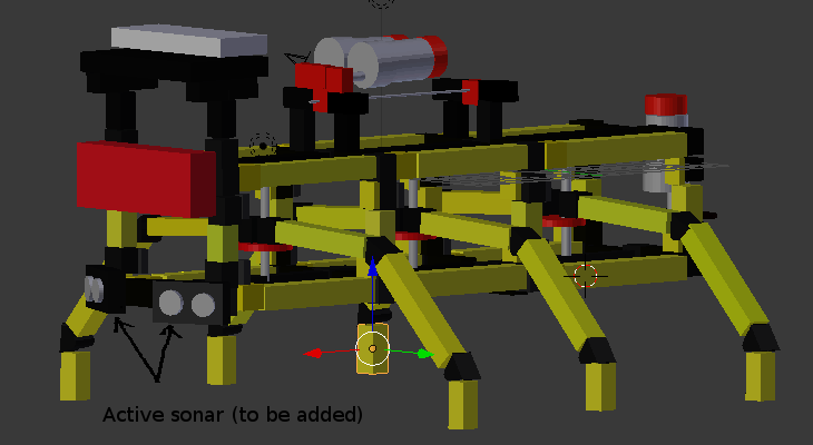
14 march 2015
It took some time but it comes to the point where the graphical model starts looking like the actual one. Screenshot of the current status:
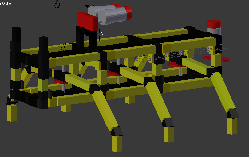
In Blender this is in 3D and can be rotated and zoomed in/out at will. In the process, I'm getting a bit more familiar with Blender (which has way too many options for me atm).
11 march 2015
It turns out that the original Robotics Toolbox as used in Matlab has a flaw in (at least) 1 inverse kinematics function: ikine3. The Scilab version is an next-to-identical port of it and so it contains the flaw as well and doesn't work. And guess what? I need it. To be continued (I hope).
10 march 2015
Today I managed to create the Mirft simulation in Scilab: 6 legs in the starting position. Next task is to get it animated using inverse kinematics.
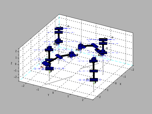
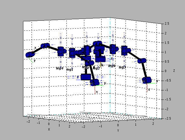
5 march 2015
Today I added an embedded systems page to show (and write about) my experiments with a classical BeagleBoard Rev C4 in more detail, just like I do with the robots.
25 february 2015
I've started modelling my walking robot Mirft both graphically and mathematically. For the graphical model I use Blender3D and for the mathematical model I use Scilab. Of course the graphical model is to see how it looks like while the mathematical model is to see if it works. Scilab Atoms offers a nice Robotics Toolkit (free and actually a port from a toolbox for Matlab) which I use. The problem I'm facing now is that the examples as shown in the Help don't work for me when I want to display 2 legs in the same simulation. As long as this doesn't work, it's no use to try the full Mirft with 6 legs in it.
12 February 2015
So, I was advised to start blogging....about my projects and me. Very short about me: I have a MSc Embedded Systems with combined specialization in Systems&Control and Robotics from Delft University of Technology, But what are my projects ? Again rather short: my robots. Those are Mirft (My insectoid robot of fiscertechnik), Mydfir (My driving fischertechnik interface robot) and the robot hand.).
Mirft
I started developing Mirft back 2006 because I wanted to build a better walking robot than the model shown in the examples from fischertechnik. As you can see from the many pictures, this has been quite a project and it's not finished by a long shot. Why ? Because of available time, ideas and material (= money). It is supposed to walk some time in the future, but before that happens quite a few problems need to be solved.
There is the horizontal movement of the legs: currently they move way too fast and I don't have a motor that is about 150:1 or slower. And before I buy, I want to be sure I buy the right motor....
Then there is the sensoring: how do I detect that the legs are at the utmost vertical position so that the motors stop ? Odometry is hard to realize with cable/rope, so light sensors are more suitable. The idea is to use a light -sensitive transistor which captures the light beam and gives a signal upon interruption when the leg is either pulled up or down. Problem with this is that I don't have enough lamps and transistors yet. Again, money can buy...
Next problem is the material to pull the legs up and down. Right now, for testing purposes, I use sisal. By far not strong enough to let it stand on its legs, but for the testing of movement it suffices. In the end it needs to be replaced by nylon.
Another issue is power. So far, its power is delivered by a standard ft-power adapter. This works as long as it remains on its scaffold. When it walks, it needs strong batteries.
Finally, for now, the material of its legs. Being made of several pieces, it remains to be seen if its strong enough to carry the weight of the robot.
To be continued....(Mirft)
Mydfir
This robot is much simpler. Directly derived from an example by ft, I just added a few ideas of my own: coloured lamps and active sonar. It works pretty well so little has to be done, or I should come up with a bright new addition :)
Last change I made was to the software: some data aquisition by writing the colour and distances returned by the robot into a file.
To be continued....(Mydfir)
The hand
This started out of curiosity: can I make a finger move, either electrically or otherwise ? Electrically proved to be hard: a small motor (no problem), some gears (no problem), chain (no problem). The problem proved to be the guidance of the chain since it got stuck continuously. So I built another finger, and used the pneumatic ft set: that works much quicker. Writing the program was easy enough, and with some mini-switches I can let each 1 of the 3 fingers move on each own or run a routine with all 3.